
Servo tester with PIC12F675

The described servo tester circuit utilizes a PIC12F675 microcontroller, which serves as the central processing unit for controlling the operation of the servo motor. The circuit is designed to test the functionality and performance of various servo motors through two primary modes: centering and sweeping.
In the centering mode, activated by the CENTRE pushbutton, the microcontroller sends a control signal to the servo, positioning it at its neutral or center point. The position can be fine-tuned by adjusting the attached potentiometer (R5 = 5K), allowing for precise control of the servo's angle. The potentiometer functions as a variable resistor, altering the voltage supplied to the servo, thus determining its position.
The sweeping mode, initiated by the SWEEP pushbutton, allows the servo to oscillate between its minimum and maximum positions. The rate of this oscillation is adjustable via the same potentiometer, providing the user with control over the sweep speed. The microcontroller employs its internal timer to generate a consistent pulse width modulation (PWM) signal with a frame duration of 20 ms, which is standard for most servo motors. The duty cycle of the PWM signal, which dictates the on/off ratio, can be modified by the user to achieve different behaviors in the servo's movement.
The passive components play crucial roles in the circuit's stability and functionality. Resistors R1 (1K), R2 (10K), R3 (82R), and R4 (10K) are used for biasing and signal conditioning, while capacitors C1 (27pF), C2 (27pF), and C3 (100nF) are employed for decoupling and filtering, ensuring stable operation of the microcontroller and reducing noise in the power supply lines. The zener diode (D1 = 4.7V) is utilized for voltage regulation, protecting the microcontroller from overvoltage conditions. The crystal oscillator (Q1 = 10MHz) provides the necessary clock signal for the microcontroller's operations, ensuring accurate timing for the PWM generation.
Overall, this servo tester circuit is a practical tool for evaluating servo performance, offering features that allow for both static positioning and dynamic sweeping, while ensuring robust operation through careful component selection and configuration.This is a simple servo tester which will comprehensively test the capabilities of almost any modern servo. It has two pushbuttons, CENTRE and SWEEP and a potentiometer which works as follows: - CENTRE Does exactly that, centers the servo, afterwards the potentiometer determines position.
- SWEEP Sweeps the servo back and forth at a rate determined by the potentiometer setting. The PIC uses its internal timer to set up a constant frame duration of 20ms and the on/off ratio is set by the user. Parts: R1 = 1K R2 = 10K R3 = 82R R4 = 10K R5 = 5K potentiometer C1 = 27pF C2 = 27pF C3 = 100nF D1 = 4,7V zener diode Q1 = 10MHz crytal IC1 = PIC12F675 🔗 External reference
Related Circuits

A 555 timer drives Q1 through Q4 with a square wave. LED1 and LED2 illuminate when an NPN or PNP transistor, respectively, is connected to the test terminals. If LED3 and LED4 light up equally as LED1 and LED2,...

Most telephone equipment today utilizes a DTMF receiver integrated circuit (IC). A widely used DTMF receiver IC is the Motorola MT8870, which is commonly found in electronic communication circuits. The MT8870 is an 18-pin IC employed in telephones and...

The simple transistor tester in Figure 1 allows for the identification of the type of transistor and aids in detecting the emitter, collector, and base of the transistor. The simple transistor tester circuit is designed to facilitate the identification of...
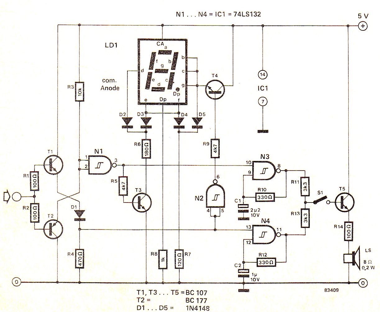
When the input signal is at logic high (1), the display indicates `H`, and the loudspeaker emits a note that is one octave higher than the low tone. The operation of the circuit can be observed in the circuit...

15V active servo power supply circuit The 15V active servo power supply circuit is designed to provide a stable and regulated output voltage of 15 volts, suitable for powering servo motors and other related devices. This circuit typically employs a...

If you have a servo and you want to test it but do not have a remote control or a dedicated tester, you can create a simple schematic for a servo tester. This circuit is based on a 555...