
operating modes

An astable circuit is characterized by its continuous oscillation, making it useful for generating clock signals in digital circuits. The square wave output can be adjusted in frequency by changing the values of the resistors and capacitors in the timing network, allowing for versatility in applications such as blinking lights or tone generation.
In contrast, the monostable circuit is designed for applications requiring a single output pulse, making it suitable for timing applications where a specific duration of output is necessary. The duration of the pulse can be controlled by the timing components, providing precise timing control for various electronic applications.
The bistable circuit, or flip-flop, serves as a memory element, maintaining its state until changed by an input signal. This functionality is crucial in digital logic design, where it can be used for data storage or state retention in sequential circuits. The inclusion of a DPDT relay in the model railway application allows for practical implementation of the bistable circuit, enabling seamless direction changes of the train based on sensor inputs.
Overall, these three types of circuits—astable, monostable, and bistable—are fundamental building blocks in electronic design, each serving distinct purposes that contribute to the functionality of various systems, from simple timers to complex digital logic applications.An Astable Circuit has no stable state - hence the name "astable". The output continually switches state between high and low without without any intervention from the user, called a `square` wave. This type of circuit could be used to give a mechanism intermittent motion by switching a motor on and off at regular intervals.
It can also be used to flash lamps and LEDs, and is useful as a `clock` pulse for other digital ICs and circuits. A Monostable Circuit produces one pulse of a set length in response to a trigger input such as a push button. The output of the circuit stays in the low state until there is a trigger input, hence the name "monostable" meaning "one stable state".
his type of circuit is ideal for use in a "push to operate" system for a model displayed at exhibitions. A visitor can push a button to start a model`s mechanism moving, and the mechanism will automatically switch off after a set time.
A Bistable Mode or what is sometimes called a Schmitt Trigger, has two stable states, high and low. Taking the Trigger input low makes the output of the circuit go into the high state. Taking the Reset input low makes the output of the circuit go into the low state. This type of circuit is ideal for use in an automated model railway system where the train is required to run back and forth over the same piece of track. A push button (or reed switch with a magnet on the underside of the train) would be placed at each end of the track so that when one is hit by the train, it will either trigger or reset the bistable.
The output of the 555 would control a DPDT relay which would be wired as a reversing switch to reverse the direction of current to the track, thereby reversing the direction of the train. 🔗 External reference
Related Circuits
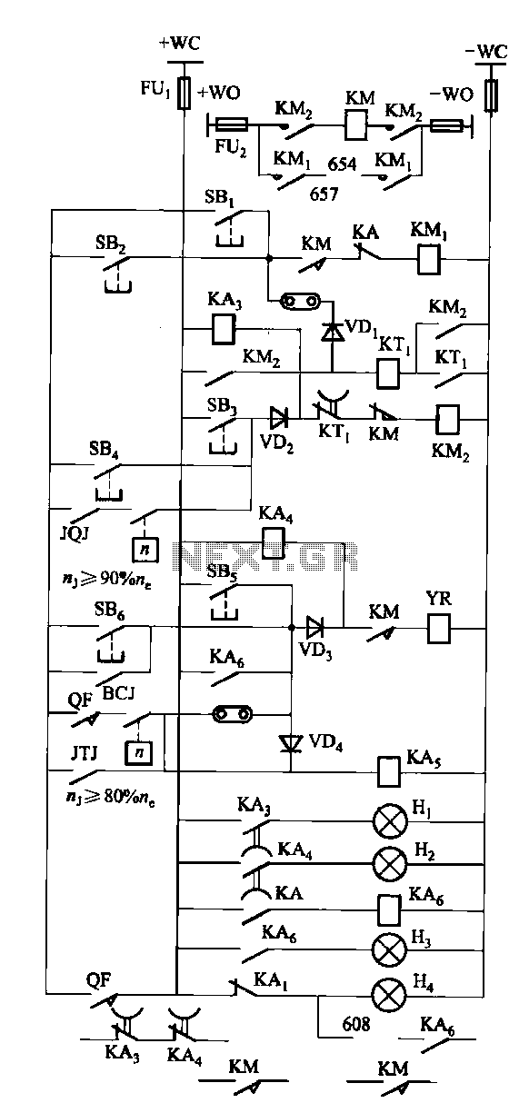
The FKL-32 type automatic thyristor excitation device is designed for synchronous generators with a terminal voltage of 400V and a capacity of 500kW and below. It is used for the automatic adjustment of excitation. The FKL-32 thyristor excitation device is...
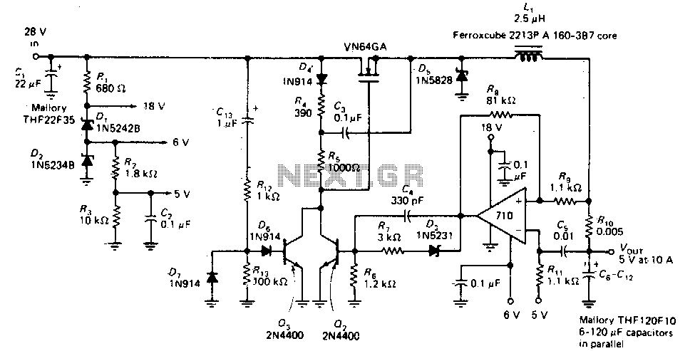
This circuit provides a regulated DC output with less than 100 mV of ripple for microprocessor applications. The required operating voltages are derived from a bleeder resistor network connected across the unregulated 28 V supply. The output of the...
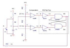
The 555 Timer IC operates in three modes: monostable, astable, and bistable/Schmitt trigger. This article will focus on its astable mode. The astable mode of the 555 Timer IC is characterized by its ability to generate a continuous square wave...
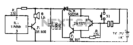
A few custom integrated circuits began to play music. When the song ends, no electricity flows through the thyristor, which then cuts off the light, causing the phototransistor to activate. The system is designed with a touchpad; each touch...
The circuit design utilizes a VHF amplifier configured to operate within the frequency range of 88 to 108 MHz, specifically for Band 2 radio applications. The VHF amplifier circuit is designed to enhance weak radio frequency signals in the specified...
There is growing interest in utilizing PC and workstation platforms for reactive sound synthesis and processing applications. However, few operating systems are designed to provide real-time performance, and vendors typically do not guarantee or specify the expected performance levels...