
The Astable-Oscillator Operating Mode in 555 Timer IC Circuit

The astable mode of the 555 Timer IC is characterized by its ability to generate a continuous square wave output without requiring any external triggering. This mode is often utilized in applications such as pulse width modulation, clock generation, and LED flashing.
In astable mode, the 555 Timer functions as an oscillator. The circuit configuration involves two resistors (R1 and R2) and a capacitor (C1) connected to the timing pins of the IC. The resistors determine the charge and discharge times of the capacitor, which in turn sets the frequency and duty cycle of the output waveform.
The formula for calculating the frequency (f) of the output signal is given by:
\[ f = \frac{1.44}{(R1 + 2R2) \cdot C1} \]
The duty cycle (D), which indicates the proportion of time the output is high versus low, can be calculated using the following formula:
\[ D = \frac{R2}{R1 + 2R2} \]
In this configuration, when the circuit is powered, the capacitor charges through both resistors R1 and R2 until it reaches approximately two-thirds of the supply voltage. At this point, the 555 Timer switches its output state to low, causing the capacitor to discharge through R2 until it drops to one-third of the supply voltage. This cycle repeats indefinitely, resulting in a square wave output.
To implement the astable mode, the following connections are made:
- Pin 1 (GND) is connected to the ground.
- Pin 2 (TRIG) is connected to the junction between R2 and C1.
- Pin 3 (OUT) provides the output signal.
- Pin 4 (RESET) is connected to VCC to disable the reset function.
- Pin 5 (CTRL) is connected to ground through a capacitor (typically 0.01 µF) to filter noise.
- Pin 6 (THRESH) is connected to the junction between R2 and C1.
- Pin 7 (DISCH) is connected to the junction between R1 and R2.
- Pin 8 (VCC) is connected to the positive supply voltage.
By adjusting the values of R1, R2, and C1, the frequency and duty cycle of the output signal can be tailored to meet specific application requirements. The versatility and simplicity of the 555 Timer in astable mode make it a popular choice for generating timing and oscillation signals in various electronic projects.The 555 Timer IC worked in three operating modes: monostable, astable and bistable/scmitt trigger. Here we will provide you with article of its astable mode. 🔗 External reference
Related Circuits
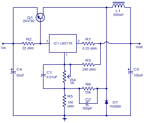
This circuit illustrates a 3A Switching Regulator Circuit based on the LM317K integrated circuit. It is designed to be simple and cost-effective. The 3A Switching Regulator Circuit utilizing the LM317K IC serves as a versatile voltage regulation solution, capable of...
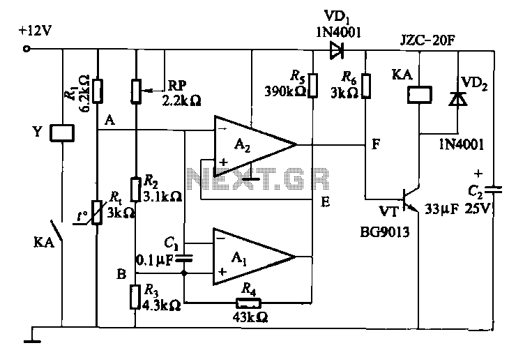
Electronic temperature control circuit for imported car air conditioners. It utilizes operational amplifiers A1 and A2, specifically the LM393 model. An adjustment potentiometer (RP) is included, allowing modification of the temperature range. The adjustment range includes a power temperature...
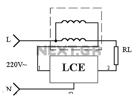
This is an application circuit of the device as illustrated in principle. In the meter, the voltage and current coils are connected to the power line, regardless of whether a load is connected. The voltage coil consistently draws power,...
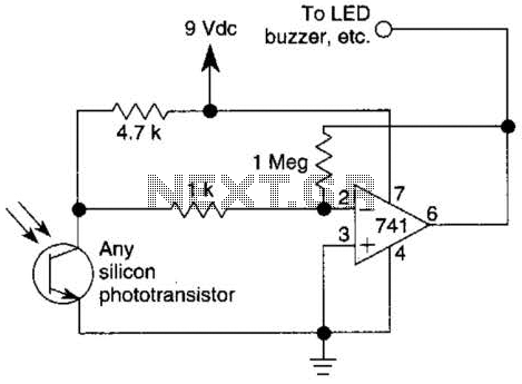
This circuit represents one of the simplest infrared (IR) receivers that can be constructed. The components are inexpensive, the layout is not critical, and a 9-V battery provides a long operational life. The described IR receiver circuit typically consists of...
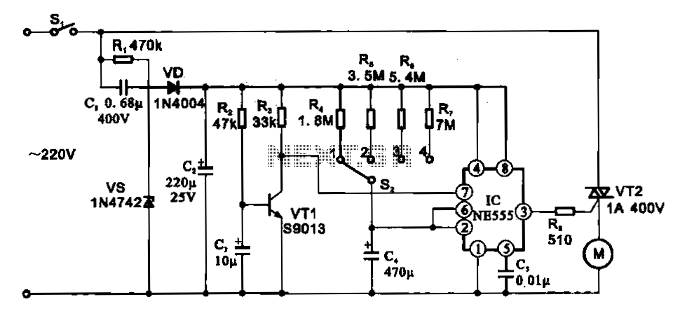
The fan motor driving circuit is depicted as a basic configuration comprising a power circuit and a motor drive circuit. The power supply circuit primarily consists of a power switch (SI), a capacitor (C1), resistors (R1), a Zener diode...

This is the design circuit diagram of an ultrasonic mosquito repeller. The circuit operates based on the theory that insects, such as mosquitoes, can be repelled by sound frequencies in the ultrasonic range (above 20 kHz). The circuit utilizes...