
Optical communication system

The described circuit functions as a light modulation system, where an LED serves as the light source. The modulation is achieved through audio signals that are input via a crystal microphone or loudspeaker, effectively encoding the audio information into light variations. The efficiency of the optical system is critical, as it directly influences the performance and range of the circuit.
To convert the LED's divergent light output into a more focused beam, either a convex lens or a concave mirror can be employed. The choice between these optical components depends on the specific application requirements, such as the desired focal length and the characteristics of the LED output. The focused beam is then directed towards a photodarlington transistor, which is known for its high sensitivity and ability to amplify small currents. This transistor serves as the light detector, converting the received light signals back into electrical signals.
The circuit is designed to operate effectively at varying distances. At close range, the light signal captured by the photodarlington transistor generates a sufficient voltage across the load resistor to drive a crystal earpiece directly. This allows for simple audio playback without additional amplification. However, as the distance increases, the strength of the received signal diminishes. In such cases, an amplifier becomes necessary to boost the signal strength before it can adequately drive a loudspeaker, ensuring that the audio output remains clear and audible even at greater distances.
Overall, this circuit exemplifies a practical application of light modulation technology, utilizing optical components and electronic amplification to facilitate communication over varying ranges.The circuit will modulate the light from the LED using a crystal microphone or a loudspeaker output. To obtain the maximum range, the optical system must be efficient (see example). Either a convex lens or a concave mirror can be used to convert the LED output into a parallel beam. The received light is concentrated onto a sensitive photodarlington transistor. At short range the signal across the load resistor is adequate to drive a crystal earpiece, for longer range an amplifier and a loudspeaker are needed.
Related Circuits
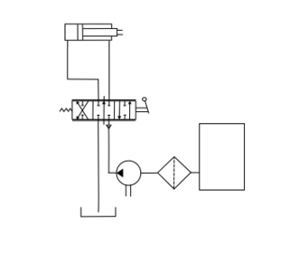
A hydraulic or hydrostatic drive system, also known as hydraulic power transmission, utilizes pressurized hydraulic fluid to drive machinery. The term hydrostatic refers to energy transfer through flow and pressure rather than the kinetic energy of the flow. This...
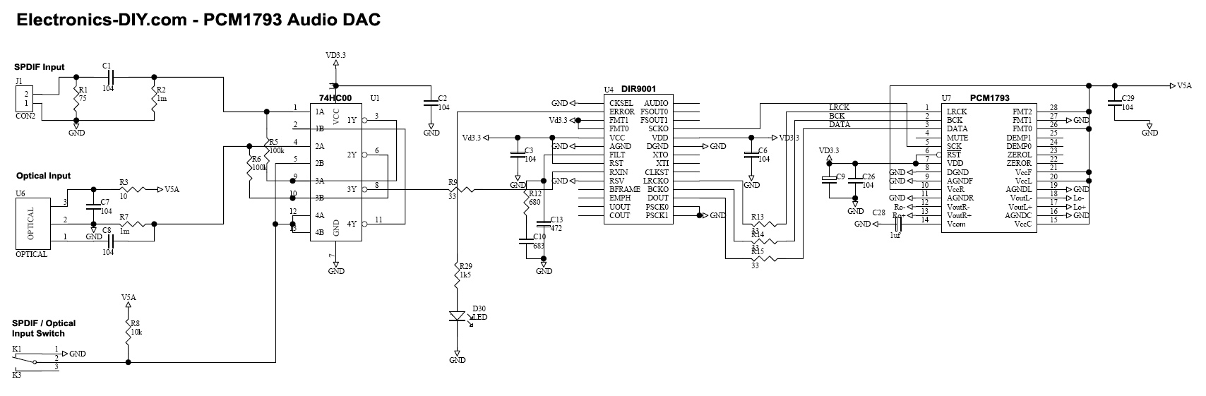
Adjusting the receiver settings in the Digital Audio menu revealed that the default setting was OPTICAL. After changing it to COAX, an improvement in sound quality was noticed. In digital audio systems, the choice between optical (TOSLINK) and coaxial (S/PDIF)...
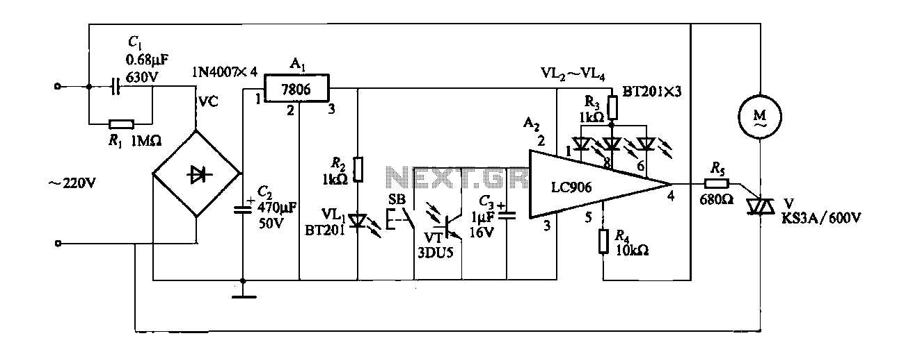
The ceiling fan speed control circuit depicted in Figure 3-6 utilizes a capacitor step-down method and a three-terminal fixed 7806 voltage regulator. It achieves fan speed control through the integrated circuit A2, which regulates the conduction angle of the...
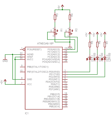
Neural networks are a broad topic. This example demonstrates how to create a basic neural sensor that takes resistive readings from multiple sensors, multiplies them by a weight factor, and then sums the results. The results are compared to...
Nowadays every institution needs automation. As a part of college automation, a project has been developed for a Voice Interactive System for College Automation. This project allows users to quickly access student attendance and marks through the telephone line...
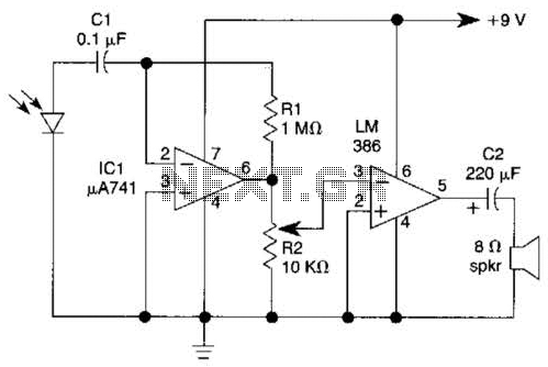
This light-wave receiver comprises a 741 operational amplifier functioning as a preamplifier and an LM386 operational amplifier serving as a power amplifier. The gain control is managed by a potentiometer labeled R2. Various types of detectors can be utilized...