
Light-Wave Voice-Communication Receiver Circuit

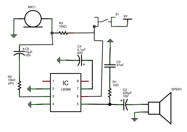
This light-wave receiver circuit is designed to efficiently detect and amplify light signals. The core components include the 741 operational amplifier, which acts as a preamplifier to boost the weak signals received from the light detectors. The LM386 then serves as a power amplifier, increasing the signal strength further for transmission or processing.
The gain control potentiometer, R2, allows for fine-tuning of the amplification level, enabling the user to adapt the circuit's sensitivity based on the specific requirements of the application. This feature is particularly important when dealing with varying light conditions or when using different types of light detectors.
Phototransistors are a popular choice for light detection due to their high sensitivity; however, they are not ideal in high ambient light conditions. In such environments, the use of a 100 kΩ series resistor is recommended to limit current and protect the phototransistor from potential damage. The circuit can also accommodate other types of light detectors, such as solar cells, photodiodes, and LEDs. These alternatives can provide reliable performance, especially when matched with the semiconductor material of the light source, ensuring compatibility and optimal operation.
Overall, this light-wave receiver circuit is versatile and adaptable, making it suitable for various applications, including remote control systems, light-based communication, and environmental monitoring. Proper selection of components and careful consideration of gain settings will enhance the circuit's effectiveness in diverse operational conditions. This light-wave receiver consists of a 741 operated as a preamplifier and an LM386 operated as a power amplifier. Potentiometer R2 is the gain control. Various kinds of detectors can be used as the front end of the receiver. Phototransistors are very sensitive, but they do not work well in the presence of too much ambient light.
A 100-kQ series resistor is required if you use a phototransis-tor. Solar cells, photodiodes, and LEDs of the same semiconductor as the transmitter all work well in this circuit.
Related Circuits
This circuit illustrates the high and mid-frequency sections of a car radio. The medium wave band I operates within the frequency range of 520 to 950 kHz, while Poland II operates between 900 and 1640 kHz. The circuit employs...
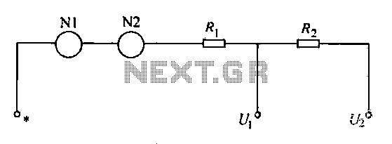
A voltmeter operates through a measuring mechanism in a specified circuit, utilizing a moving coil in series with additional resistance. The fixed coil is denoted as N1, while the moving coil is designated as N2. The additional resistances are...
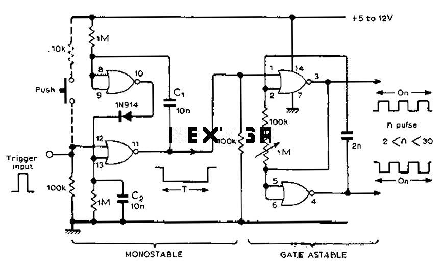
Each trigger input can produce a fixed number of pulses, with the range being from 2 to 30. The specific number is determined by the frequency-controlled settings of 1 megohm. A monostable gated unsteady power supply circuit can be...
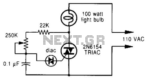
A phase-controlled dimmer delays the triac turn-on to a selected point in each successive AC half cycle. This circuit is suitable only for incandescent lamps, heaters, soldering irons, or universal motors that have brushes. A phase-controlled dimmer is an electronic...
A button is utilized as a push-to-talk switch. While it generally functions correctly, there is a significant delay of approximately five seconds before any audio output is heard upon pressing the button. The described circuit involves a push-to-talk switch, which...
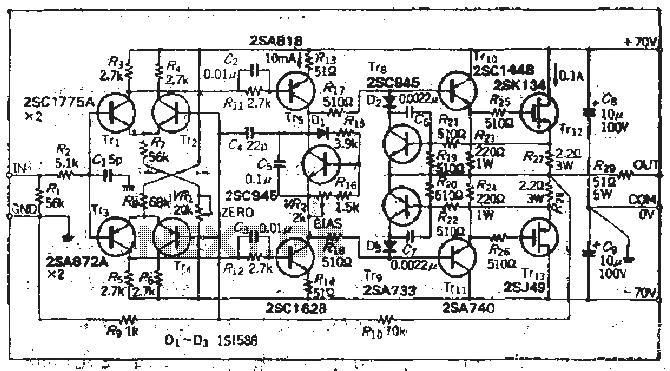
The south circuit consists of four parts, arranged in descending order: an NPN transistor dynamic garbage device (T1), a PNP transistor differential amplifier (T2, T3) forming a double differential circuit, two balanced output amplifiers with opposite phase, and a...