
Optical Interruption Sensor

The infrared optical interrupter circuit utilizes the NE567 tone decoder IC, which integrates a local oscillator and PLL decoder, making it efficient and compact. The local oscillator's frequency is set to 40 kHz through the careful selection of resistor RT and capacitor CT, which define the timing characteristics of the oscillator. The output from this oscillator is fed into Q1, a low-power PNP transistor, which acts as a switch to control the infrared LED.
The infrared LED emits modulated light, which is then detected by Q2, the photodetector. When the LED's light is unobstructed, Q2 detects the modulated infrared signal, generating a corresponding output signal at pin 3 of the NE567. This output signal indicates that the path between the emitter and receiver is clear, resulting in a high output from the IC. Conversely, when an opaque object obstructs the light path, the signal is interrupted, leading to a low output state.
The feedback network between pins 1 and 8 is crucial for maintaining output stability and preventing oscillations, which can occur due to noise or rapid changes in the detected signal. This feature is particularly important when interfacing with inductive loads, such as relays, where mechanical inertia can introduce delays and fluctuations in the output.
The versatility of this circuit allows it to work with various LED and photodetector combinations, although using matched pairs can enhance performance by optimizing the range and sensitivity of the interrupter. The circuit can be suitable for applications such as object detection, counting systems, or safety barriers, where the interruption of a light beam must be reliably detected. Using only an 8-pin IC and a few discrete components, you can build the infrared optical interrupter. The NE567 tone decoder has all the necessary circuit elements: a local oscillator, a PLL decoder, and a 100-mA output-drive capability. The local oscillator, which is tuned to 40 kHz by RT and CT, drives Ql, a universal low-power silicon pnp transistor (such as a 2N3906, BC559, or ZTX500).
Ql drives the IR-emit-ting diode. The receiving part of the circuit surrounds the ICs internal PLL input at pin 3. When the pho-todetector, Q2, detects the oscillating IR light beam, the 40-kHz signal appears at pin 3 of the IC, Under this condition, the circuit locks and the ICs output is high. When something opaque comes between the LED and Q2, the 40-kHz signal doesn"t reach the PLL input, and the ICs output goes low.
The feedback network between pins 1 and 8 prevents the output from chattering. If you connect this circuit to a high-inertia load (such as a mechanical relay), the output doesn"t tend to oscillate and you can eliminate these feedback components. The circuit works with virtually any LED-photodetector pair, but matched pairs allow for longer distances between the emitter and receiver.
The table lists some of the best choices.
Related Circuits
Temperature indicators and temperature-based products have garnered significant interest due to their numerous applications and various possible solutions, each presenting unique advantages and disadvantages. This concept focuses on a sensor interface that delivers high accuracy while minimizing board space....
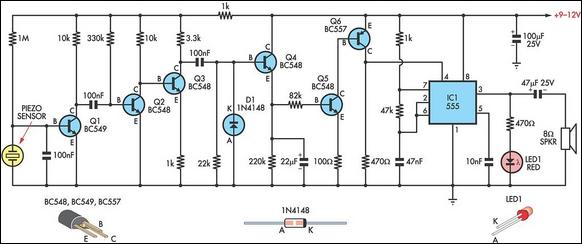
This circuit employs a thin piezoelectric sensor to detect vibrations caused by knocking on a surface, such as a door or table. It amplifies and processes the sensor's signal to trigger an alarm for a predetermined duration. The piezoelectric...
The Diploma Final Year Project represents the culmination of the learning process, where it is essential to apply previously acquired engineering and personal skills. The assessment significantly influences decisions regarding readiness for graduation. This final year project spans an...
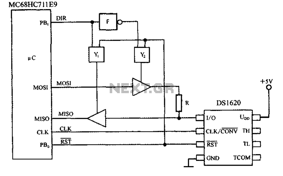
This circuit features a three-wire serial interface for smart temperature sensors, specifically the DS1620, along with an SPI bus interface circuit. The DS1620 is a high-accuracy digital temperature sensor that communicates over a three-wire interface, which consists of a data...
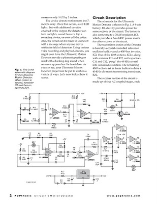
Some ultrasonic range finders for a project. Most commercial sensors like Parallax's PING sensor and similar products are quite expensive, especially when multiple units are needed. Therefore, a decision was made to build the sensor independently. The theory behind...

This liquid level sensor circuit employs a common operational amplifier IC 741 configured as a comparator. When the sensor detects that the two fluid levels (which can be represented by two small pieces of PCB or similar conductors) are...