
optoisolated adapter

The use of a triac optocoupler has the added advantages of using fewer parts than other optocoupler designs and can use the power from the flash`s trigger circuit to fire the SCR switch instead of a separate power source. The adapter circuit can be inserted into the lines inside the flash unit going between the flash trigger circuit and the flash unit`s contacts as shown below.
Since there are only 4 small parts in this circuit, there is a good chance that you can build it right into the available space inside the flash unit`s case. o- | - (+) Flash hot-shoe contacts | Flash trigger circuit o- | - (-) |/ Cut and insert adapter circuit below +-+ R2 (-) o-(1)-+ +-(6)-//-+-o Flash Trigger (+) | | OPTO1 | | 5.
6K |A To Hot-Shoe | _|_ _|_ | _|_ (and camera) | _\_/_-> _\_/_/_\_ (5)NC _\_/_ SCR1 | | | | / | 400V, 6A (+) o-+ +-(2)-+ | | |G | K (RS#276-1020) | | NC(3) +-(4)-+ | / | +-+ | R1 | Optotriac +-o Flash Trigger (-) 330 / | MOC3010 | (RS#276-134) | | o o (+) (-) To 6V Battery (Flash unit battery pack) The camera shutter shorts the hot-shoe contacts, causing current to flow from the 6V battery through the IR-emitting diode at pins 1 & 2 of the OptoTriac. The current is transferred via light pulse which switches on the triac at pins 4 and 6 of the OptoTriac which is powered by the voltage from the flash trigger circuit.
Current flows into the gate of the SCR, switching it on and causing discharge of the flash trigger through the anode and cathode of the SCR. The 330 ohm resistor (R1) limits the current through the hot-shoe to about 18 mA, and the 5. 6k ohm resistor (R2) limits the current through the triac to about 40 mA. You may need to use a different value for R2 for your particular flash and SCR, since this is based on a 218 V trigger voltage.
The triac can handle a larger current (1. 2 A peak), but SCR`s typically only use a small gate current for triggering. The circuit with component values shown seems to work reliably (at least so far) for this particular combination of Canon digital camera and slave flash. Others may be quite different. Some info can be found at Kevin Bjorke`s: Non-Canon Strobe Page with a List of Trigger Voltages. Just knowing the trigger voltage isn`t really enough information as it doesn`t imply anything about the available current.
Adding an input buffer using a transistor or CMOS gate would eliminate this as a concern. SCRs and triacs should be driven hard when they are controlling high current sources to make sure they turn on quickly and minimize time where they are passing significant current with a significant voltage drop. The optotriac`s output is current limited so this isn`t much of an issue. However, the SCR discharges the trigger capacitor through the trigger transformer and this could amount to several A switched in a few microseconds.
A gate current 10 to 20 times the minimum spec in the datasheet is recommended so long as this doesn`t exceed the maximum rating in the datasheet. In any case, the worst that will happen is that the SCR will fail or become unreliable after running with marginal gate drive - no great loss considering its cost.
🔗 External reference
Related Circuits

The TOP269EG off-line switcher integrated circuit (IC), designated as U1, can be utilized in a flyback configuration to create a simple and highly efficient power adapter for notebook laptops. The TOP269EG features an integrated 725 V MOSFET and a...
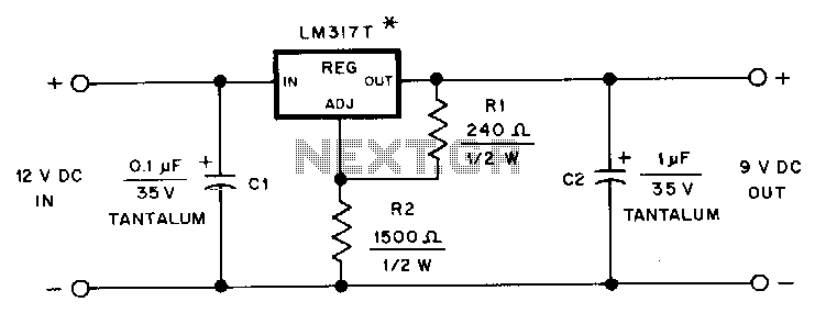
This adapter provides a regulated 9-V source for operating a Kenwood TR-2500 hand-held transceiver in a vehicle. The mounting tab of the LM317T is electrically connected to its output pin, which should be considered during the construction of the...
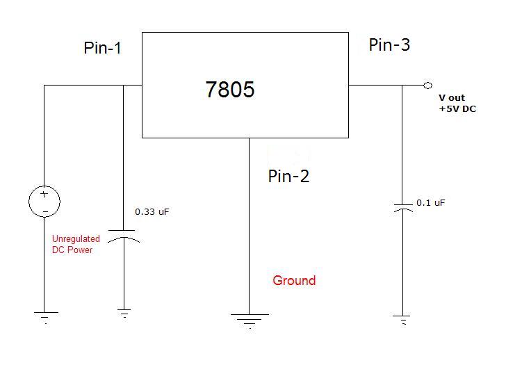
Many different devices require DC power and thus need an I.T.E power supply. I.T.E stands for "Information Technology Equipment." An example of such a device is an iPod speaker system that is no longer functional, which originally came with...

The baseband audio input originates from the pole of switch S1 in the stereo decoder and is coupled to IC1 (a CA3089) via a 78.6 kHz bandpass filter composed of capacitors C1 and C2, along with inductor L1. IC1...

The AC adapter circuit is designed for portable digital products, converting low voltage DC into 220V AC. It features a circuit configuration for a switch power drill utilizing the oscillation IC LD7575 as a switch. This IC operates after...

The CGA to SCART adapter offers significant advantages, including the absence of a separate power source and minimal external components, which can be conveniently integrated into the SCART connector. The signals from the R, G, and B pins of...