
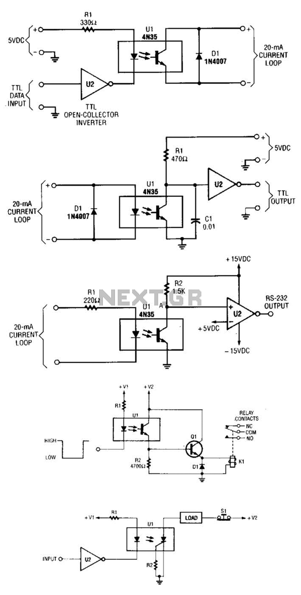
Optoisolator

The circuit protects a solid-state relay from overloads by limiting current, automatically disconnecting the load after detecting a short circuit, and generating a fault-condition output signal. During normal operation, the controlling unit sets the flip-flop, IC1, which activates transistor Q1. When Q1 is activated, current flows through the input of the solid-state relay, thereby engaging the relay. In the event of an overcurrent or fault condition, the excessive load current passing through the relay generates sufficient voltage across sense resistor R5 to activate one of the optoisolators, IC4A or IC4B. The output transistor of the optoisolator redirects current away from the input of the solid-state relay, thereby limiting the current that can pass through its output. If the overload condition is severe, the optoisolator raises the input of the Schmitt trigger above its threshold, which clears the flip-flop and deactivates the solid-state relay. Resistor R2 serves two purposes: it keeps the input of the Schmitt trigger below a maximum of 5 V to prevent latchup and acts as part of an RC filter in conjunction with capacitor C1. This RC filter mitigates the risk of spurious triggering of the Schmitt trigger. The output from the flip-flop can be used to signal overload conditions to the controlling microprocessor.
The circuit design incorporates a solid-state relay (SSR) for switching applications, ensuring rapid response times and high reliability. The inclusion of a flip-flop (IC1) allows for stable control of the relay, effectively latching it in the on state until an overload condition is detected. The transistor Q1 acts as a switch that controls the relay's activation in response to the flip-flop's output, ensuring that the relay only engages when the system is operating normally.
The use of a sense resistor (R5) is critical for monitoring the current flowing through the relay. When the current exceeds the predefined threshold, the voltage drop across R5 activates one of the optoisolators (IC4A or IC4B). This component serves to isolate the control side of the circuit from the high-power side, providing safety and preventing damage to sensitive components. The optoisolator's output transistor is configured to divert current, effectively protecting the solid-state relay from excessive current that could lead to failure.
The Schmitt trigger plays a vital role in providing a clean and stable output signal in the presence of noisy conditions. By ensuring that the input voltage remains below 5 V, resistor R2 helps to prevent unintended latchup of the Schmitt trigger, which could result in erratic behavior. The RC filter, formed by R2 and capacitor C1, serves to smooth out any rapid voltage fluctuations that may occur, thus maintaining the integrity of the triggering mechanism.
Finally, the output from the flip-flop can be interfaced with a microprocessor, allowing for real-time monitoring of the relay's status. This feature enables the controlling unit to take appropriate actions in response to overload conditions, enhancing the overall reliability and safety of the circuit. The design is suitable for various applications where protection against overloads is critical, ensuring the longevity and functionality of the solid-state relay and associated components. The circuit protects a solid-state relay from overloads. The circuit limits current, automatically disconnects the load after detecting a short circuit, and develops a fault-condition output signal. In normal operation, the controlling sets the flip-flop, IC1, which turns on transistor Ql. When Ql turns on, current flows through the solid-state relay"s input, thus activating the relay. If an overcurrent or fault condition occurs, the excessive load current flowing through the relay develops enough potential across sense resistor R5 to turn on one of the optoisolators, IC4A or IC4B. The optoisolator"s output transistor diverts current around the solid-state relay"s input, which limits the current that the relay"s output can pass.
If the overload is severe enough, the optoisolator pulls the input of the Schmitt trigger above its threshold, thus clearing the flip-flop and turning off the solid-state relay. R2 has two functions: It keeps the input of the Schmitt trigger below 5 V max. to prevent latchup, and it forms an RC filter in conjunction with CI. The RC filter prevents spurious triggering of the Schmitt trigger. You can use the output of the flip-flop to signal overload conditions to the controlling uP.
Related Circuits
A circuit for isolating a variable resistor is presented. An optoisolator, which consists of an LED and a photo-conductive cell (or photoresistor), is utilized. The current flowing through the LED regulates its brightness, which subsequently dictates the resistance between...