
Optoisolator And Optocoupler Interface circuits

The circuit design employs an optoisolator to achieve electrical isolation between different parts of the system while facilitating control of a variable resistor. The LED within the optoisolator is activated by a controlled current, which is influenced by the arrangement of the resistors R1 and R2. R1 functions as a current-limiting resistor to ensure that the LED operates within safe parameters, preventing damage due to excessive current flow. The potentiometer, which can vary its resistance, allows for fine-tuning of the LED brightness, thus adjusting the resistance encountered between terminals A and B.
In scenarios where the load is too high for the optoisolator to handle directly, a relay can be integrated into the circuit. This relay acts as a switch that can be activated by the output of the optoisolator, allowing it to control larger currents or voltages safely. Schematic A demonstrates this configuration, highlighting the relay's role in managing heavy loads. Conversely, schematic B presents a simpler circuit that may suffice for lighter applications but lacks the capability for automatic shutoff, which could lead to potential hazards or inefficiencies in the system.
Overall, this circuit exemplifies the use of optoisolation in electronic designs to achieve safe and effective control over variable resistances, accommodating both light and heavy load scenarios through appropriate component selection and configuration. A circuit for isolating a variable resistor is shown. An optoisolator that has an LED arid a photo-conductive cell (or photoresistor) is used. The current through the LED controls its brightness, which in turn determines the resistance between terminals A and B. The LED current is set by the voltage of the dc power supply and the value of the two resistors (Rl and R2), The fixed resistor (Rl) is used to limit the current to a maximum of 20 mA (when the resistance of the potentiometer, is set to zero ohms), otherwise, the LED might burn out.
Very heavy hmdx, which can`t be powered directh by an optoisolator, might require the use of a rela as shown in A. You can sometimes i;el a way with using a circuit like that shown in B, hut it won`t turn itself off.
Related Circuits
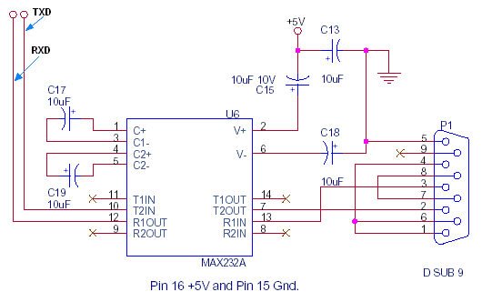
This document outlines the standard configuration for interfacing a microcontroller, such as the 8051, with a PC using RS232 through the MAX232A. The UART or serial port was absent in the 8049 and 8749 microcontrollers, which were predecessors to...

The circuit is a high-power car audio amplifier schematic. It functions as a car audio amplifier using the PA02 and LH0101 integrated circuits (ICs). Each IC delivers an output power of 30W with an 8-ohm impedance. The part list...
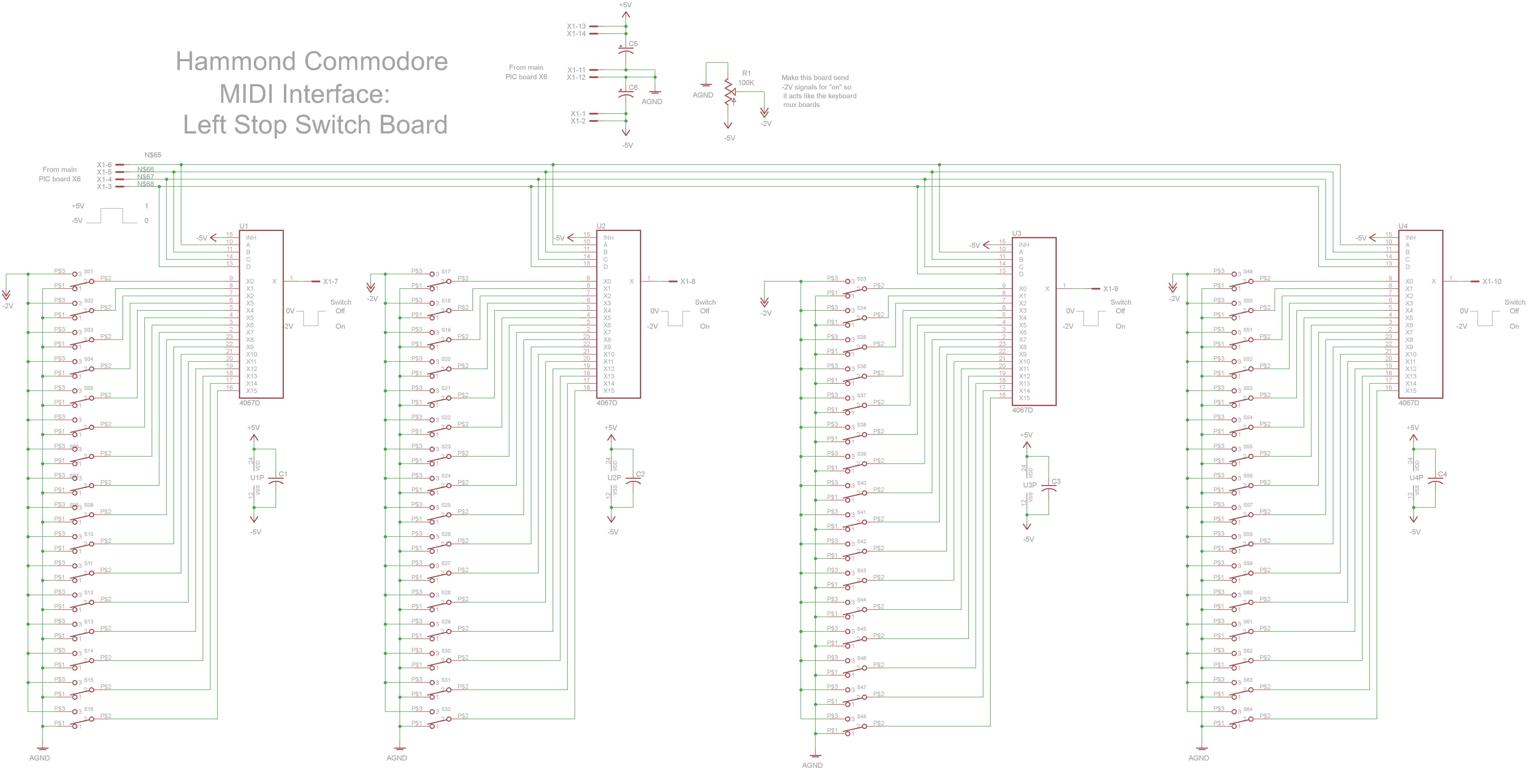
The schematic circuit board features switches that output -2V when activated and 0V when deactivated. Four 4067 multiplexers combine the 64 switch signals into 4 signals that return to the main PIC board. The circuit design incorporates a series of...
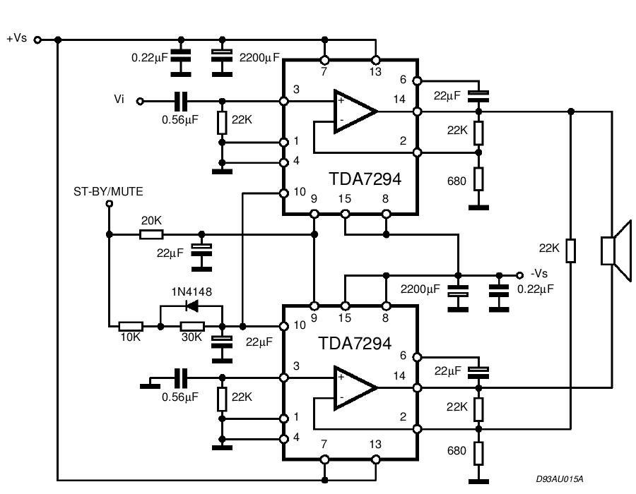
The TDA integrated circuit series is highly regarded and widely utilized in amplifier designs and projects. TDA audio amplifier circuits are primarily produced by Philips and SGS-THOMSON. The most commonly used ICs include the TDA2030 and TDA2003 for small...
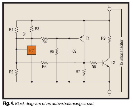
As the market seeks lighter, more compact wireless and portable devices with innovative features packed into increasingly constrained spaces, there is a concurrent pursuit for the next power supply innovation—a powerful, compact, long-lasting, economical, and safe battery. Although advancements...

A field strength meter utilizing a biased Schottky detector employs a temperature-compensated Schottky diode within an amplified, untuned field strength indicator powered by two AA cells. This device indicates the relative field strength of RF fields ranging from a...