
oscillator HEF4060B counter doesnt count
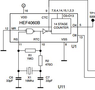
The oscillator circuit described utilizes a crystal resonator to generate a stable frequency signal. The crystal's role is to provide a precise oscillation frequency determined by its physical characteristics. In this case, the initial 16 MHz crystal failed to start oscillating, which can be attributed to various factors including incorrect load capacitance, parasitic capacitance from the breadboard, or layout issues affecting signal integrity. When the 16 MHz crystal was replaced with an 11 MHz crystal, the circuit functioned correctly, indicating that the oscillator stage and supporting components were operational.
The output signals from the oscillator are fed into a 14-stage counter, which is designed to count pulses. The presence of a signal at pin 9 suggests that the oscillator is producing output, but the counter's failure to count indicates a potential issue with the counter's configuration or connection. The grounding of the MR pin suggests that the reset functionality is working correctly, allowing for normal operation when the counter is provided with clock pulses.
The update regarding the circuit's performance on a different breadboard indicates that layout and connection quality significantly impact oscillator behavior. The successful operation at lower frequencies suggests that the original breadboard may have introduced excess inductance or capacitance, which can adversely affect high-frequency operations. The challenges faced with the 16 MHz crystal, specifically its dependence on removing the capacitor to oscillate, highlight the importance of matching the load capacitance to the crystal specifications, which are typically found in the manufacturer's datasheet.
In conclusion, the performance of oscillator circuits is highly sensitive to layout, component values, and environmental factors. Proper testing and adjustments, including the use of lower frequencies and careful consideration of parasitic elements, are essential for achieving reliable operation. The lack of a datasheet for the crystal complicates the tuning process, emphasizing the need for thorough documentation and understanding of component specifications in electronic design.The first problem is with the 16Mhz xtal the thing doesn`t even start to oscillate. But that`s a secondary problem. If I replace 16MHz xtal with a 11MHz one (or less) the oscillator starts. I can see with the `scope that I have a nice 11Mhz sinusoidal waveform on the pin 11, and I see a not-so-nice square-ish waveform on the pin 9 (so, I imagine t hat oscillator parts works fine). The MR pin (Master Reset) is connected to GND. So, everything should work as expected. Problem is that I have fixed values on the output pins! The 14 stage counter is receiving a signal from the oscillator stage (as I can see it on the pin 9) but doesn`t count. Pins are almost always zero. And when some pin is at 1, if I raise MR, pin goes to 0. So, the logic and Master Reset is working, but the counter is not. UPDATE: I`ve rebuilt the circuit with a different layout on a different breadboard, and now it works with 4MHz, 11MHz and 14.
1MHz (from 9 to 15V). The 16Mhz one still have some problem, because it starts to oscillate only if I remove the capacitor between PIN11 and ground. I tried with some random values, from 1 to 1000pF, and nothing. But I think that this could be a problem caused by the breadboard as apalopohapa said. Moreover I don`t have the datasheet for the specific xtal, so I don`t know how to find right capacitor values.
Maybe this should be another question. The problem could be related to testing at near the device`s maximum frequency on a breadboard. Breadboards add inductance to all the pins and force large loops in your wiring. They also make proper power bypassing difficult because you have to use caps with long leads. Test at lower frequencies and see what happens. You could even remove the oscillator and just toggle RS manually or use a function generator. Note from the datasheet that the lower end of the maximum frequency at 12V is about 12 MHz (the typical value is much higher, but you can`t really count on it because it is not guaranteed), but this was probably rated with device properly bypassed on a pcb. Lastly, the parasitic capacitance that the breadboard adds will affect the oscillator circuit, so you may have to adjust for this.
Like I said in a comment before, you may need to start looking for the improbable, or things that you take for granted because they usually don`t fail: the breadboard, cables, etc. 🔗 External reference
Related Circuits
A simulation of a 27 MHz transmitter circuit is to be conducted using PSPICE. The circuit diagram is provided as Figure 1 in the following content. The 27 MHz transmitter circuit typically consists of several key components, including an oscillator,...
A simple high-efficiency Colpitts oscillator is utilized in higher frequency ranges, specifically above 50 MHz. Colpitts oscillators are preferred as stray circuit capacitance is in parallel with the desired feedback capacitance, preventing undesirable spurious resonances that may occur with...
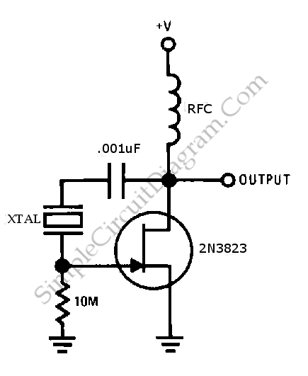
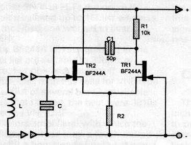
This is a simple JFET pierce crystal oscillator. A wide frequency range of crystals can be used with this circuit without requiring any modifications. The JFET pierce crystal oscillator is a versatile circuit that utilizes a Junction Field Effect Transistor...
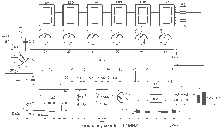
The MK50398 is one modern decimal counter up/down of six tens, with control of screen LED of seven segments and flip-flop of storage. Counter it can measure additive and abstractively. The IC MK50398 is ideal for manufacture frequency counter...
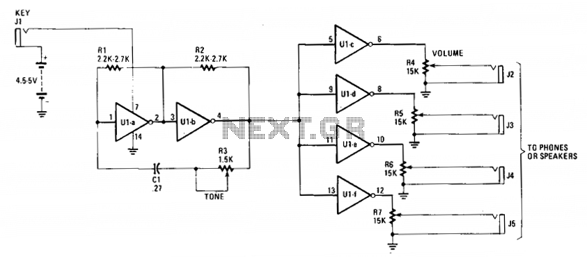
The cost-effective 7404 hex-inverter provides sufficient amplification to accommodate a broad spectrum of transducers. Engaging the switch completes the battery circuit, supplying four to five volts to the 7404. The bias for the first two inverter amplifiers (Ula and...
Individuals interested in home construction may occasionally need to measure the inductance of small coils. This task can be challenging, as commercially available equipment with sufficient accuracy is often prohibitively expensive for occasional use in an amateur workshop. Affordable...