
Code practice oscillator

The circuit utilizes the 7404 hex inverter as its main amplification component, which is capable of transforming input signals into inverted outputs. The design begins with the activation of a switch that connects the battery to the circuit, ensuring a stable voltage supply of four to five volts. This voltage is crucial for the operation of the 7404, enabling it to amplify signals from various transducers effectively.
In the initial stage, the first two inverter amplifiers, Ula and Ulb, receive their biasing through resistors Rl and R2. These resistors establish a feedback mechanism that stabilizes the input signal for optimal performance. The feedback loop is further enhanced by the combination of the capacitor (C1) and rheostat (R3), which not only fine-tunes the phase of the output signal but also helps in managing the frequency response of the circuit.
As the signal passes through Ulb, it is then transmitted to the subsequent inverter amplifiers, Ulc to Ulf. This cascading configuration allows for greater amplification of the audio signal, which is essential for driving output devices such as headphones or speakers. The final audio output is controlled through the volume control potentiometers (R4-R7), which can be adjusted to suit the user’s preference. The selection of potentiometer values is flexible, ranging from 1500 ohms to 10,000 ohms, with lower resistance values being particularly advantageous for applications involving speakers or low-impedance headphones. Overall, this circuit design exemplifies a robust and versatile approach to audio amplification using the 7404 hex inverter.The inexpensive 7404 hex-inverter has enough amplification to handle a wide range of transducers. Closing the key completes the battery circuit and applies four to five volts to the 7404. Bias for the first two inverter amps (Ula and Ulb) comes from the two resistors, Rl and R2, connected between their inputs and outputs. The capacitor and rheostat (R3/C1) close the feedback loop from the input to the properly-phased output.
The signal leaving Ulb drives the remaining four inverter amplifiers, Ulc through Ulf; they, in turn, drive the phones or speakers. The volume control potentiometers, R4-R7, may have any value from 1500 ohms to 10,000 ohms. The smaller values work best when speakers, or low impedance phones, are used.
Related Circuits
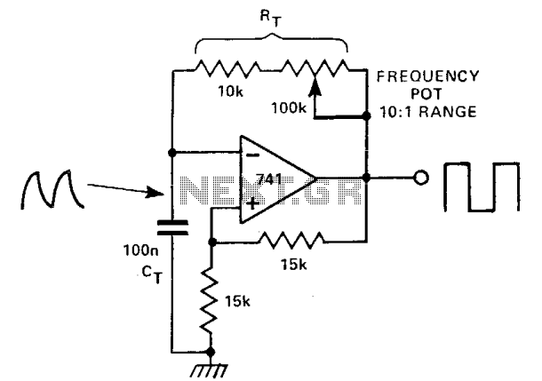
This circuit features two feedback paths around an operational amplifier (op-amp). One feedback path is a positive DC feedback that creates a Schmitt trigger, while the other incorporates a capacitor-resistor (CR) timing network. When the output voltage is +10...
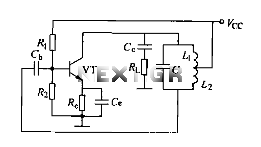
A feedback oscillator circuit utilizing inductance is presented, featuring the 3DG3 transistor. The component parameters reference values include: 1) transistors 3DG6, 2) resistances R1 at 91 kΩ, R2 at 11 kΩ, and R3 unspecified, 3) capacitance values of C...
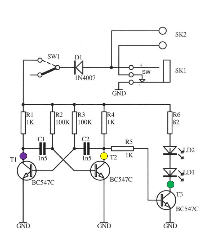
The schematic circuit presented below illustrates an infrared transmitter. The infrared beam is emitted in a nearly line-of-sight manner towards another device equipped with an infrared receiver. The displayed waveforms represent the output voltages from two intermediate stages (purple...

A common issue in crystal sinusoidal oscillators is the excitation of unintended modes of the quartz crystal, which diminishes the spectral purity of the oscillator. This issue is particularly significant in overtone crystals, especially for low-voltage applications. In such...
A 10 MHz crystal typically exhibits an impedance of 4 ohms at its series resonance and 40 kiloohms at its parallel resonance. To minimize sideband noise, the power dissipated in the crystal must be substantial; the design presented here...
This simple stereo encoder circuit schematic is built with two ICs, MMC4066E and MMC4047, along with one transistor, BC547B. The audio output is taken from pins 2 and 3 of IC1. The stereo encoder circuit utilizes the MMC4066E, which is...