
oscillator Is this a suitable sine wave osc? how would I control the frequency

The LM386n-1 is a low-voltage audio power amplifier designed for use in battery-powered applications. It typically operates with a power supply range of 4 to 12 volts and is capable of delivering up to 1 watt of output power into an 8-ohm load. This IC is suitable for applications that require a compact design due to its small footprint and minimal external components.
To control the frequency of the output signal, it is essential to focus on the timing components used in the circuit. The frequency can typically be adjusted by changing the values of capacitors and resistors in the feedback network of the amplifier. In many configurations, the frequency is determined by the RC time constant, which is influenced by both resistance and capacitance values.
If the goal is to modify the pitch, it may be necessary to experiment with the capacitors in the feedback loop. For instance, increasing the capacitance will lower the frequency, while decreasing it will raise the frequency. Additionally, the resistors in the feedback path can also be adjusted; however, their interdependence suggests that a systematic approach to changing one component at a time will yield the best results.
In terms of implementing an Automatic Gain Control (AGC), various options are available. One common approach is to use a diode-based AGC circuit, which can help maintain a consistent output level by adjusting the gain based on the input signal amplitude. Another option could be to integrate a dedicated AGC IC that automatically adjusts the gain based on the detected signal level.
Ultimately, the selection of components for the AGC will depend on the specific requirements of the application, including the desired response time and the dynamic range of the input signal. Careful consideration of these factors will enhance the overall performance of the final circuit design.As I`m working from a single power supply and I`m trying to keep the design small, I`ve been using the LM386n-1 IC. Also, how would you suggest I control the frequency, which component value should be changed to achieve this - I`ve tried messing with all the resistors to change the pitch, but theyall seem to be interdependent.
And this is what my implementation looks like, I don`t have a suitable incandescent bulb so I`ve just replaced it with a 1K © pot. I`m still not sure what I`ll use in the final circuit as AGC, suggestions are welcome. 🔗 External reference
Related Circuits
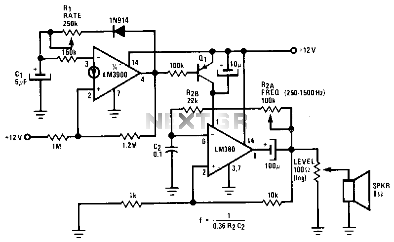
The LM380 functions as an astable oscillator, with the frequency set by R2 and C2. By adding Q1 and driving its base, the output of an LM3900 is configured as a second astable oscillator. This setup gates the output...
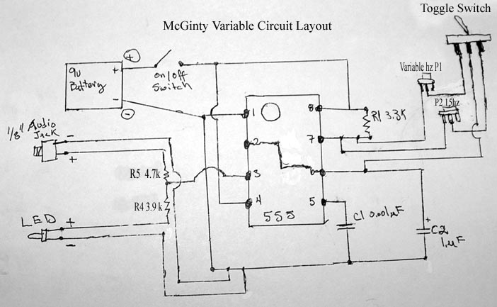
Building your own Zapper. It requires one capacitor of 1 microfarad (C2), preferably unpolarized to eliminate concerns regarding positive and negative terminals. If a polarized capacitor is used, the longer leg indicates the positive side; refer to the schematic...
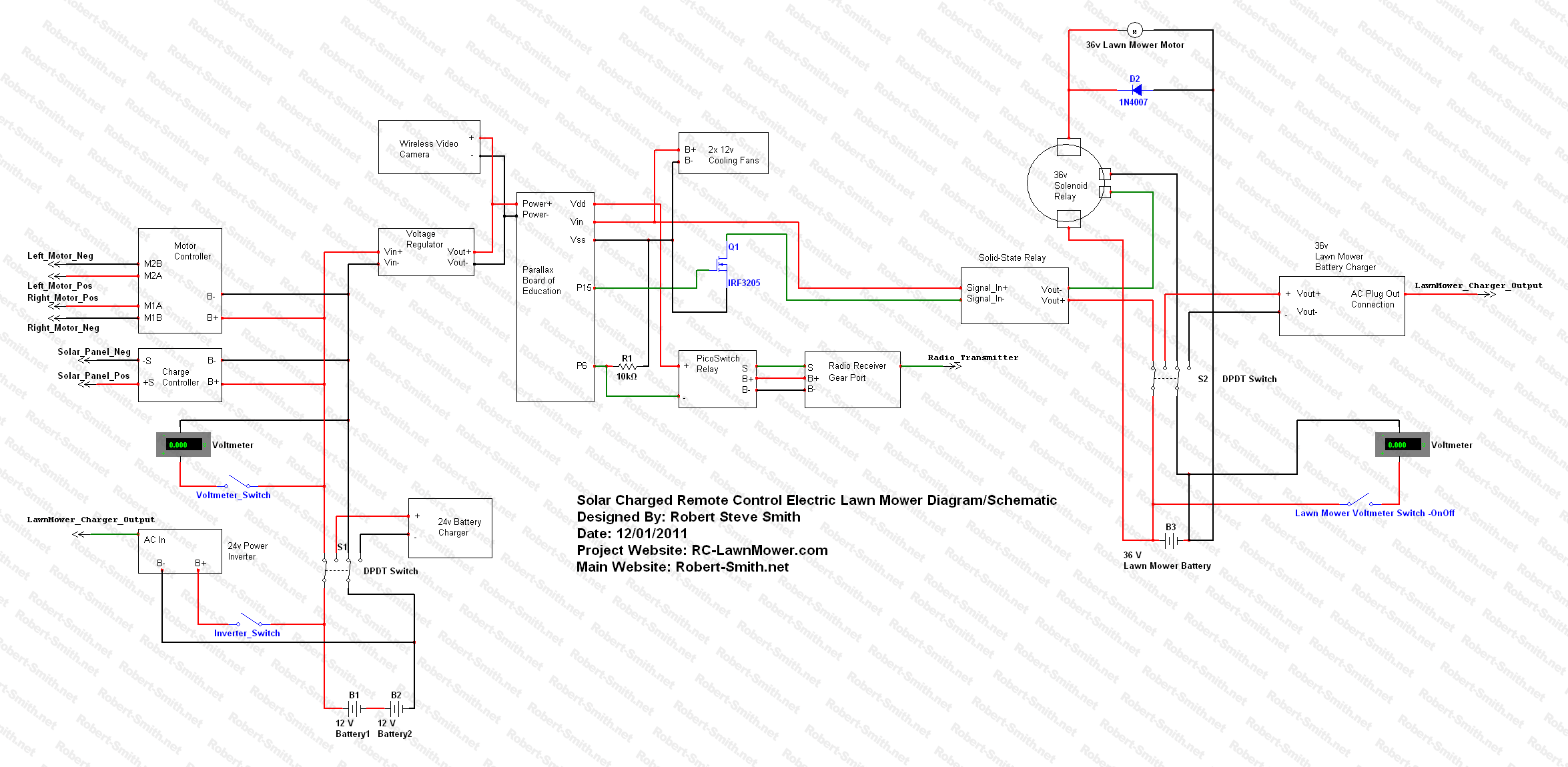
Develop a device that operates independently of gasoline, is user-friendly, can serve as a backup energy source, and allows for sharing the construction process with others. The instructional video series is structured similarly to a previous large project that...
A frequency doubler can be constructed using a single 4069 hex inverter IC, resulting in an output pulse train with a frequency that is twice that of the square wave input signal. The frequency doubler circuit utilizing the 4069 hex...
XP power plug, FU fuse, ST temperature control, T1 low-voltage transformers, S1, S2 door interlock switch, S3 threshold control switch, RT thermal sensor, K1, K2 relay, EL furnace light, M1 wheel motor, M2 fan motor, T2 high-voltage transformer, C...
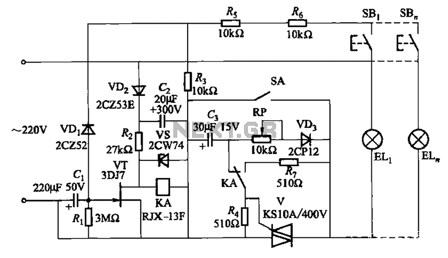
The circuit illustrated in Figure 2-50 utilizes a field effect tube and a combination of electronic components to create a unique self-lighting controller. The working lamp remains illuminated at a reduced brightness rather than being completely turned off, which...