
frequency doubler with 4069

The frequency doubler circuit utilizing the 4069 hex inverter IC is an efficient method for generating a signal at double the frequency of the input. The 4069 is a quad inverter, which means it contains four independent inverter gates, allowing for versatile designs.
To construct the frequency doubler, the circuit typically consists of one inverter from the 4069 IC, connected to the input square wave signal. The output of this inverter is then fed into a second inverter, creating a feedback loop that generates oscillations. The feedback is achieved through a resistor-capacitor (RC) network, which determines the timing characteristics of the circuit.
The input square wave signal is applied to the first inverter, which inverts the signal. The output from the first inverter is then connected to an RC network, consisting of a resistor (R) and capacitor (C). This RC network introduces a phase shift that is crucial for frequency doubling. The output of the RC network is then fed into the second inverter, which further inverts the signal.
The result is a pulse train at the output that has a frequency that is twice that of the original input signal. The output can be observed using an oscilloscope, which will display a waveform with a frequency that is double that of the input square wave.
This frequency doubler circuit is useful in various applications, including signal processing, modulation, and clock generation in digital circuits. The simplicity of using a single IC makes it an attractive solution for designers looking to implement frequency doubling in their projects. Proper selection of the resistor and capacitor values is critical, as it affects the performance and stability of the frequency doubling process.This frequency doubler using a single 4069 hex inverter IC, a frequency doubler can be constructed to give an output pulse train whose frequency is twice that of a squarewave input signal.. 🔗 External reference
Related Circuits
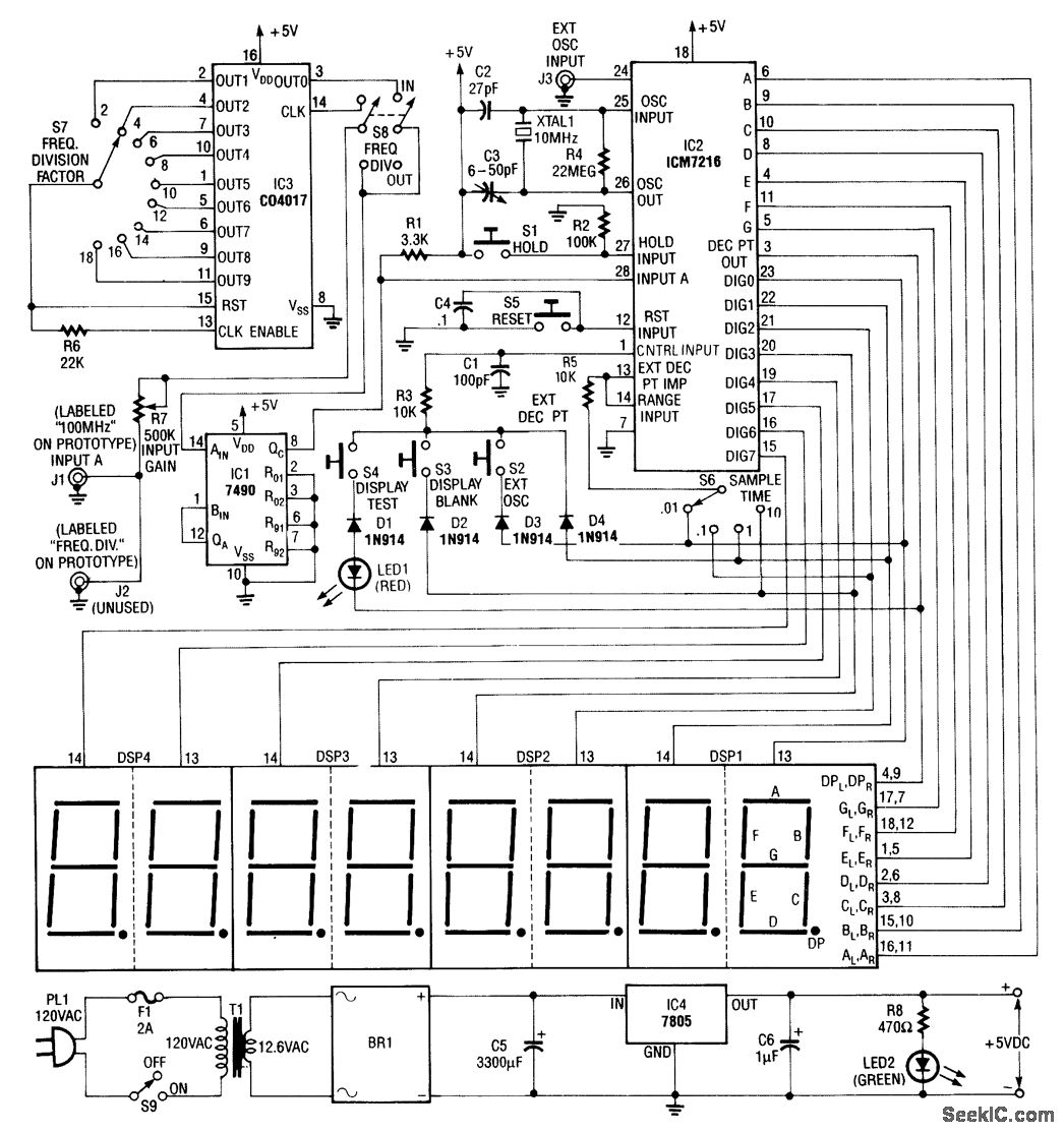
Built around an Intersil 7216 frequency-counter IC, this counter features a basic frequency range of 10 MHz, complemented by a 100-MHz prescaler and an additional frequency divider (IC3). This divider further extends the counting range by dividing the frequency...
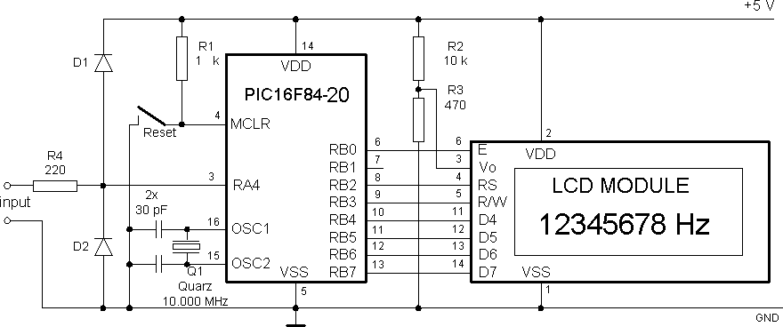
The circuit comprises a Microchip PIC 16F84 microcontroller and an LCD text module. The author claims that this counter can measure frequencies ranging from 400 Hz to 50 MHz. A faster version, the 20 MHz PIC 16F84A-20I/P, was utilized,...
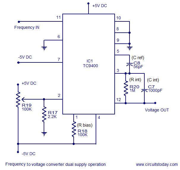
A simple frequency to voltage converter circuit designed around the TC9400 F to V / V to F converter IC. Dual and single supply versions are provided. The TC9400 is a versatile integrated circuit that converts frequency signals into corresponding...
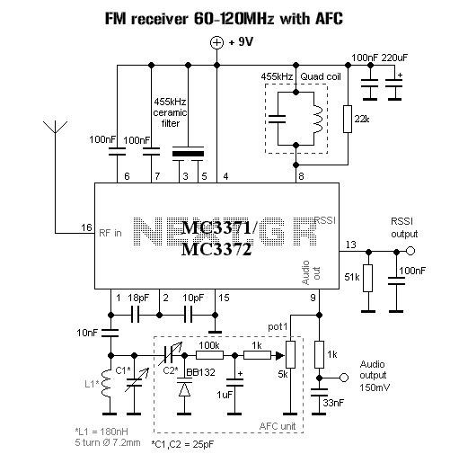
This is a measurement I did on a FM receiver (MC3372). I have plotted the output DC-bias as a function of the IF (Intermediate Frequency) frequency. At 455kHz you can see that I have 5.5V DC bias. When I...
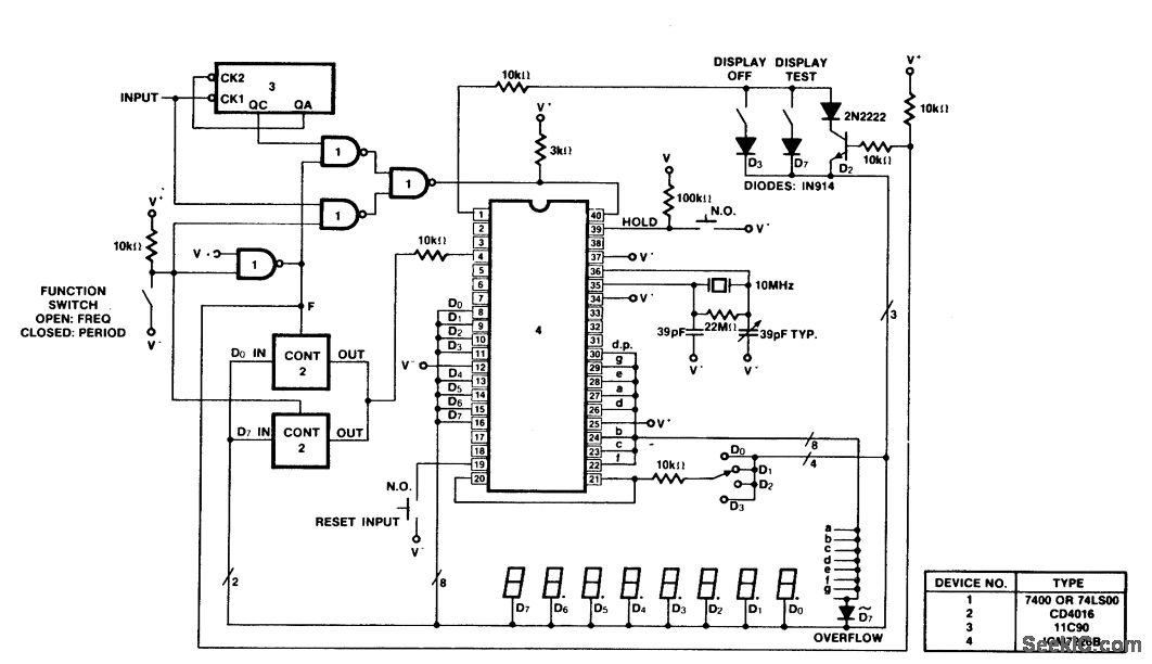
A 100 MHz frequency and period counter is constructed using the Intersil ICM7226B in a 40-pin DIP package. This circuit incorporates a CD4016 analog multiplexer to route the digital outputs back to the function input. The CD4016 operates as...
A low-frequency test oscillator designed for testing tone controls and conducting experiments. The low-frequency test oscillator serves as a versatile tool in audio engineering, particularly for evaluating tone control circuits and facilitating various audio experiments. This device generates sinusoidal waveforms...