
Oscillator with frequency doubled output

The current-controlled oscillator (CCO) operates by generating an output frequency that is dependent on an external control current. In this specific configuration, the feedback mechanism is crucial for frequency doubling. By connecting a portion of the output from pin 5 back to pin 3, the oscillator can effectively double its output frequency. This feedback creates a condition where the oscillator's output frequency becomes twice the original frequency, denoted as 2 f0.
The quadrature detector plays an essential role in this process. It is designed to detect phase differences and can thus be utilized as a frequency doubler in this application. The output from the quadrature detector at pin 8 reflects the doubled frequency, enabling various applications that require higher frequency signals.
In practical implementations, careful consideration should be given to the values of the components involved in the feedback loop, as they will influence the stability and performance of the oscillator. Additionally, the characteristics of the square-wave output must be analyzed to ensure that the feedback does not introduce unwanted harmonics or distortions that could affect the integrity of the doubled frequency output. Proper tuning and calibration of the circuit may be necessary to achieve optimal performance.The current-controlled oscillator frequency can be doubled by applying a portion of the square-wave output at pin 5 back to the input at pin 3, as shown. In this manner, the quadrature detector functions as a frequency doubier and produces an output of 2 f0 at pin 8.
Related Circuits
This page features a replacement circuit for the LM3909 LED Flasher / Oscillator using discrete components. The circuit is functionally the same as the integrated LM3909 but has a minor variation of the components used. Naturally the circuit will...
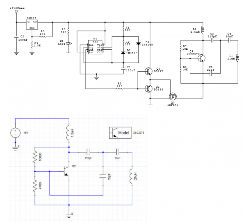
An LC oscillator is driven by pulses generated by a 555 IC-based oscillator. The LC oscillator is constructed around a 2SC2078 transistor. The circuit diagram is illustrated in Fig. 1, along with an Ansoft Designer simulation. The measured and...
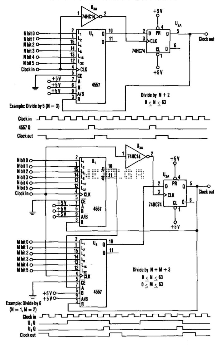
This divider utilizes a variable-length shift register, a type-D flip-flop, and an inverter. The clock signal is connected to the clock input of the flip-flop, while the output of the shift register is connected to the D input of...
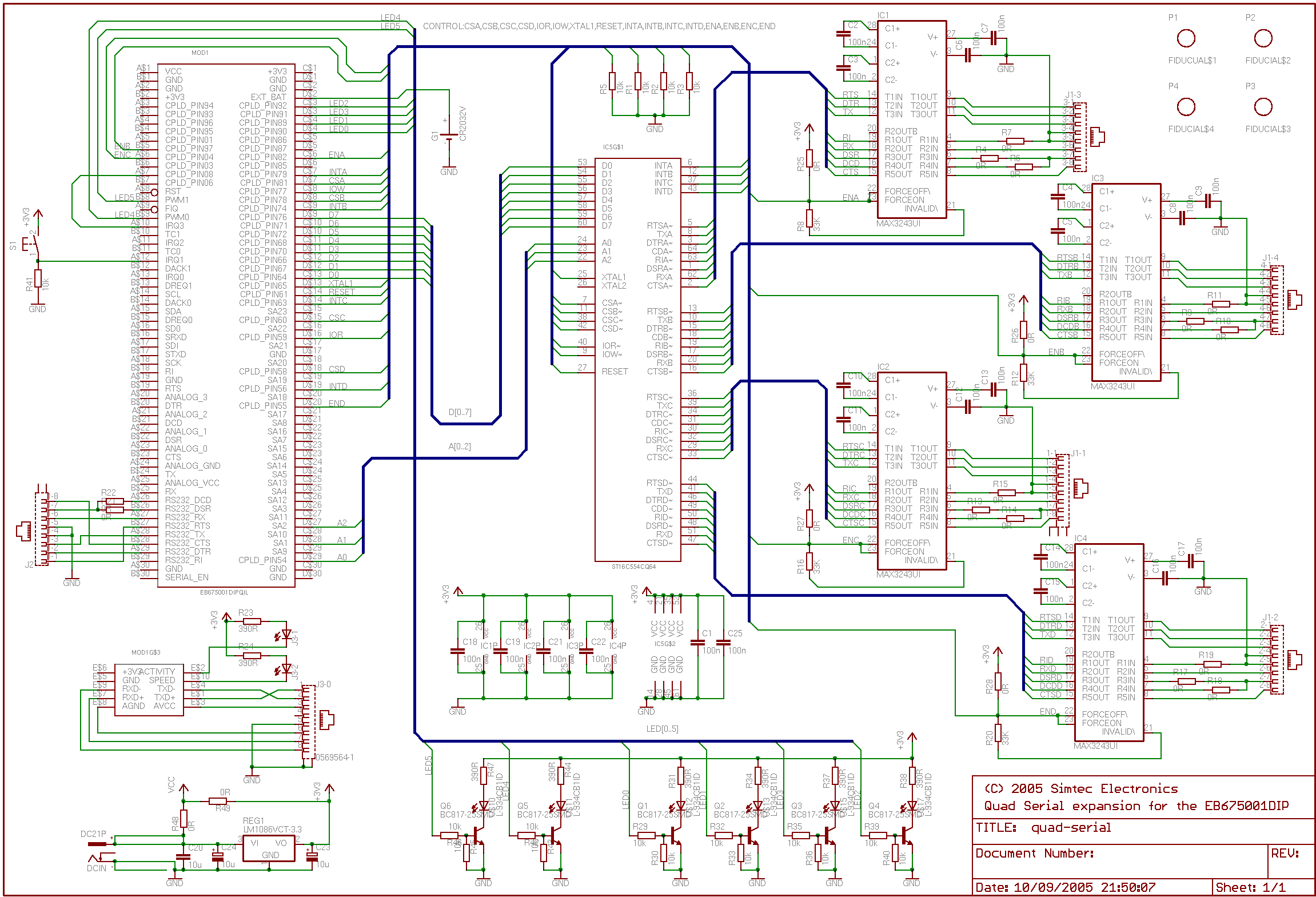
This application note outlines the creation of a basic framebuffer with PAL composite TV output for the EB675001DIP. The design employs a minimal number of additional components to facilitate this display. A user-configurable CPLD is utilized to provide all...
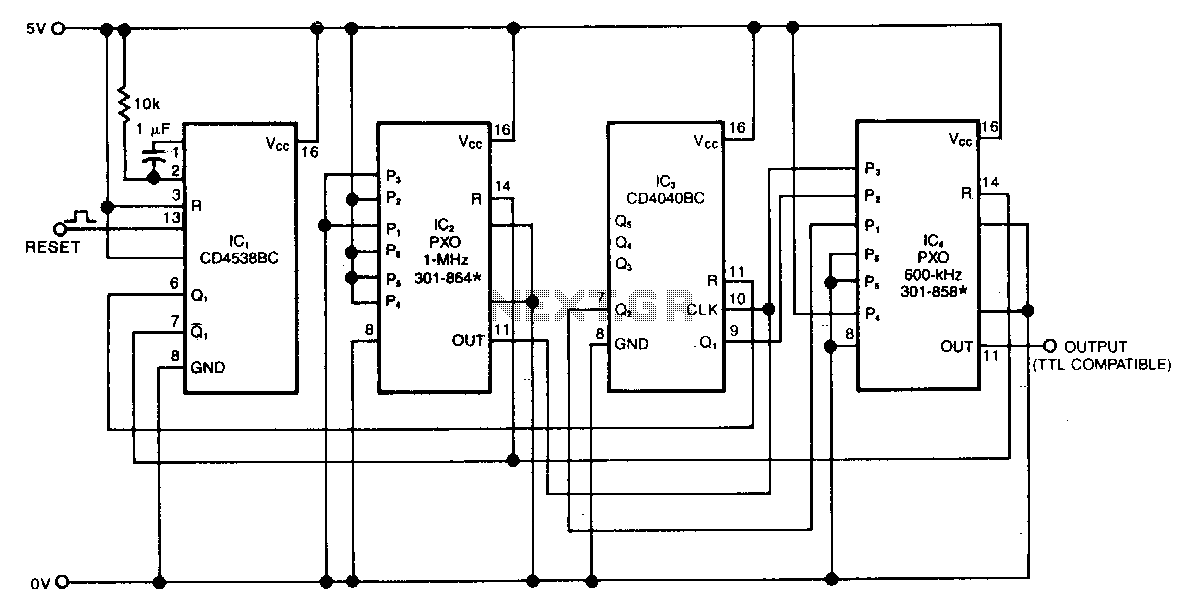
The swept-frequency oscillator provides a cost-effective source of discrete frequencies for testing digital circuits. This configuration generates an 80-second sequence of eight frequencies, with each frequency maintained for 10 seconds. The dwell time and the number of frequencies can...
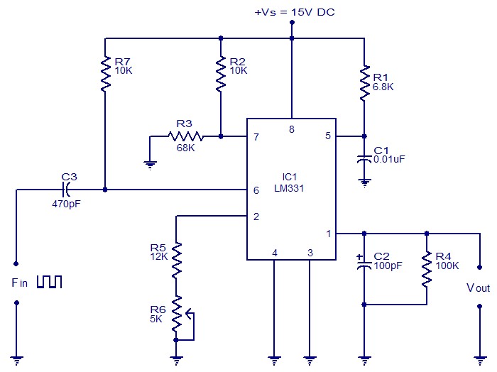
The following circuit illustrates a Frequency Voltage Converter Circuit. This circuit is based on the LM331 IC and operates with a supply voltage of 15V DC. The Frequency Voltage Converter Circuit utilizes the LM331 integrated circuit, which is designed for...