
Oscillator With Quadrature Output Using 567 IC

An oscillator circuit is a fundamental component in various electronic systems, designed to generate a continuous, oscillating signal, typically in the form of a sine wave or square wave. These circuits are essential in applications such as clock generation, signal modulation, and waveform generation.
The quadrature oscillator specifically refers to a type of oscillator that produces two output signals that are 90 degrees out of phase with each other. This phase relationship is critical in applications such as phase-locked loops (PLLs), quadrature amplitude modulation (QAM), and in the generation of complex waveforms.
A typical quadrature oscillator may utilize components such as operational amplifiers, resistors, capacitors, and sometimes inductors. The design often employs feedback mechanisms to maintain stability and ensure the desired frequency of oscillation. The frequency of the output signal can be adjusted by changing the values of the resistors and capacitors in the circuit.
In practical applications, quadrature oscillators are used in communication systems, where they help in the demodulation and modulation processes, allowing for efficient signal transmission and reception. Additionally, they can be found in signal processing applications, where they facilitate the manipulation of signals in both time and frequency domains.
Overall, the oscillator circuit is a versatile and crucial element in electronic design, enabling the generation of periodic signals necessary for a wide range of technological applications.Oscillator circuit is an electronic circuit that produce a periodic signal. The term quadrature refers to a fourth (1/4) phase shift of full wave cycle (1/4 of.. 🔗 External reference
Related Circuits

This design circuit is a tachometer circuit based on the LM2907 integrated circuit, which can provide zero-crossing data to a digital system. At each zero crossing of the input signal, the charge pump alters the state of capacitor C1...
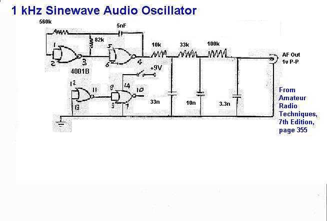
This circuit consists of a CMOS square wave oscillator on a frequency of approximately 1 kHz. The RC filter, which has a roll-off frequency of 500 Hz, filters the harmonics, providing a sine-wave output. The described circuit features a...
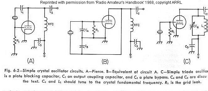
The frequency of a crystal-controlled oscillator is maintained with high precision through the use of a quartz crystal. The frequency is primarily determined by the dimensions of the crystal, particularly its thickness, while other circuit parameters have minimal impact....
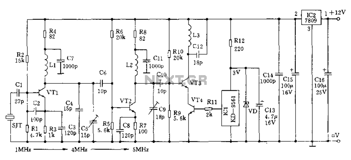
The crystal frequency stabilization of a frequency modulation circuit is illustrated below. The frequency modulation (FM) circuit utilizes crystal frequency stabilization to ensure precise frequency control and stability. This process involves the use of a quartz crystal oscillator, which...
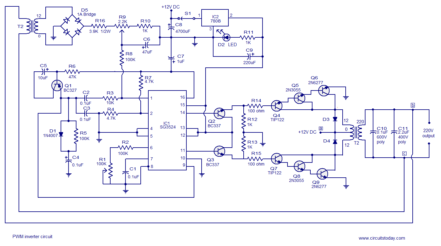
A simple PWM inverter circuit utilizes the SG3524 integrated circuit. This PWM inverter is designed for a 12V input, providing a 220V output with a maximum output power of 250 watts. The output power can be extended further. The described...
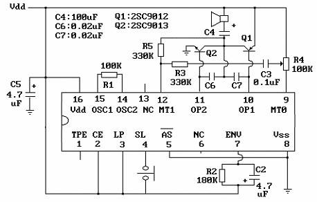
The core component of this circuit is the UM3481 integrated circuit (IC), which operates with a 1.5-volt battery. It is suitable for applications such as electronic doorbells, toys, melody clocks, and music boxes. The UM3481 is engineered to play...