
FM oscillator frequency stabilization circuit diagram

The frequency modulation (FM) circuit utilizes crystal frequency stabilization to ensure precise frequency control and stability. This process involves the use of a quartz crystal oscillator, which provides a highly accurate and stable frequency reference. The crystal's natural resonant frequency is leveraged to maintain the desired output frequency of the FM circuit, minimizing drift due to temperature variations and other environmental factors.
In the schematic, the crystal oscillator is typically connected to an amplifier stage, which boosts the output signal to the required level for modulation. The output from the crystal oscillator feeds into a frequency modulator, where the carrier signal is modulated by the information signal. This modulation can be achieved using various methods, including direct frequency modulation or phase modulation.
Feedback mechanisms may also be integrated into the design to further enhance stability. For instance, a phase-locked loop (PLL) can be employed to lock the output frequency to the crystal reference, ensuring that any variations are corrected in real time. This feedback loop consists of a phase detector, low-pass filter, and voltage-controlled oscillator (VCO), which work together to maintain the output frequency in alignment with the crystal oscillator.
Overall, the implementation of crystal frequency stabilization in FM circuits is critical for applications requiring high fidelity and low distortion, such as in communication systems, broadcasting, and audio transmission. The reliability of the crystal oscillator contributes significantly to the overall performance and efficiency of the frequency modulation circuit.Crystal frequency stabilization of frequency modulation circuit is shown below:
Related Circuits

This is a design of the circuit diagram for an RS422 interface. Connector K1 is connected to the serial port of the PC, and power for the PC side of the circuit is obtained from the signal lines DTR...
This project is a piece of test equipment. It's a square wave oscillator with 6 selectable frequencies from 1Hz to 100kHz, incrementing in decade values. Its most useful application is as a Signal Injector for radios and TVs. A...
The LM2889 is designed to interface audio and video signals to the antenna terminals of a television receiver. It consists of a sound subcarrier oscillator, an FM modulator, a video clamp, and RF oscillators and modulators for two low-VHF...
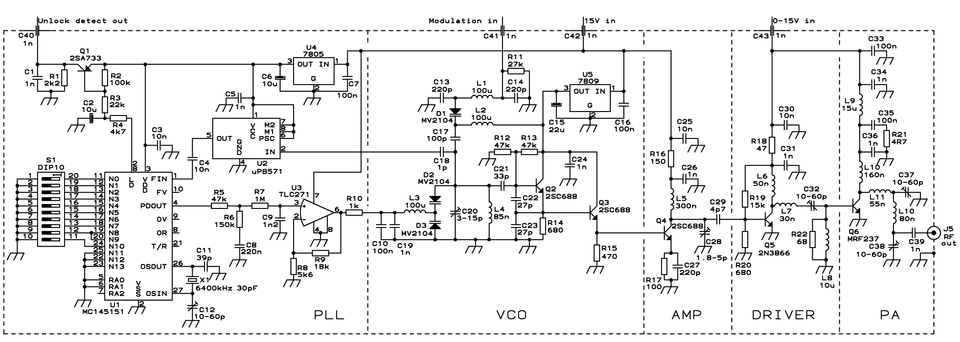
The PLL transmitter exciter is designed to provide a stable, low noise, frequency-selectable RF signal, which is amplified to a controllable output power sufficient to drive a power amplifier. It utilizes a PLL frequency synthesizer based on the MC145151,...
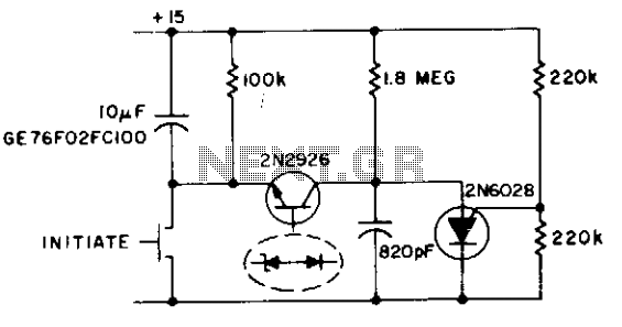
This circuit functions as both an oscillator and a timer. The 2N6028 transistor remains in an 'on' state due to the excessive holding current flowing through the 100 kΩ resistor. When the switch is briefly closed, the 10 µF...
This document details the AT Keyboard Interface and AT Keyboard Protocols. It includes an example of a Keyboard to ASCII decoder utilizing a 68HC705J1A microcontroller. The AT Keyboard Interface is a standard communication protocol used primarily in personal computers to...