
6.5Mhz Vfo Circuit

The circuit described incorporates fixed-value capacitors, specifically disc ceramic types, which are known for their stability and reliability in various electronic applications. Capacitors C1, C4, C5, C6, and C8 are categorized as NPO ceramic or polystyrene, materials that exhibit low dielectric loss and minimal capacitance change with temperature variations, making them suitable for high-frequency circuits.
Capacitor C2 serves as a 25-pF ceramic trimmer, allowing for fine-tuning of capacitance values to achieve desired circuit performance. Capacitor C3 is a 15-pF miniature air variable capacitor, providing adjustable capacitance which is beneficial in tuning applications, particularly in radio frequency (RF) circuits.
The resistors utilized in this schematic are rated at ¼ watt and are either carbon film or composition types, chosen for their stability and accuracy in current limiting and voltage division applications.
The RF chokes included in the design are miniature units from Mouser Electronics, specifically model No. 43LR103. These components are essential for suppressing high-frequency noise and preventing unwanted oscillations in the circuit.
Inductor L1 is constructed using 32 turns of #28 enamel wire wound on an Amidon Assoc. T50-6 (yellow) toroid. This toroidal inductor design minimizes electromagnetic interference and optimizes inductance, making it suitable for RF applications. Inductor L2 consists of 25 turns of #28 enamel wire on an Amidon FT-37-61 ferrite toroid, which is designed to enhance performance in higher frequency ranges due to its superior magnetic properties.
Overall, the schematic diagram of the Variable Frequency Oscillator (VFO) integrates these components effectively to create a stable and tunable oscillator circuit, essential for various RF applications. The choice of materials and component specifications reflects a design focused on achieving high performance and reliability in electronic circuit operations. Fixed-value capacitors are disc ceramics. CI, C4, C5, C6, and C8 are NPO ceramic or polystyrene. C2 is a 25-pF ceramic trimmer and C3 is a 15- pF miniature air variable capacitor. The resistors are -W carbon film or composition. The RF chokes are miniature Mouser Electronics No. 43LR103 units. For LI, use 32 turns of #28 enamel wire on an Amidon Assoc. T50-6 (yellow) toroid. L2 has 25 turns of #28 enamel wire on an Amidon Ft-37-61 ferrite toroid. Schematic diagram of the VFO. Fixed-value capacitors are disc ceramic. C1.C4, C5, C6, andC8areNP0 ceramic or polystyrene. C2 is a 25 pF ceramic trimmer and C3 is a 15 pF miniature air variable. Resistors are V* watt carbon film or composition. The RF chokes are miniature Mouser Electronics No. 43LR103units. For L1 use 32 turns of No. 28 enamel wire on an Amidon Assoc. T50-6 (yellow) toroid. L2 has 25 turns of No. 28 enamel wire on an Amidon FT-37-61 ferrite toroid.
Related Circuits
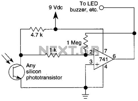
This circuit represents one of the simplest infrared (IR) receivers that can be constructed. The components are inexpensive, the layout is not critical, and a 9-V battery provides a long operational life. The described IR receiver circuit typically consists of...
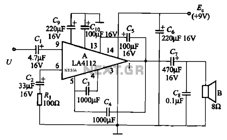
Audio power amplifier circuit utilizing the LA4112 integrated power amplifier along with additional components as shown in the figure. The audio power amplifier circuit based on the LA4112 integrated power amplifier is designed to deliver high-quality audio amplification for various...
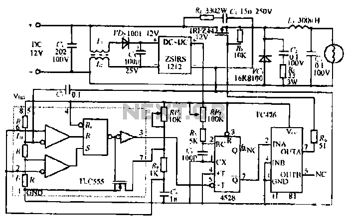
The circuit utilizes a Bute CD12V Lee power MOSFET transistor (BU1RF744) that operates in a switching mode, turning on and off repeatedly. The output voltage is influenced by the characteristics of the MOSFET, which is designed for efficient performance....

This design outlines a fire alarm circuit that utilizes a light-dependent resistor (LDR) and a lamp to detect fire. The alarm is activated by sensing the smoke produced during a fire. When smoke is present, it obstructs light from...
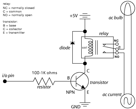
The schematic illustrates the Relay Wiring Circuit Diagram used to control an air conditioner or other high-current devices via a microcontroller. The relay wiring circuit serves as an interface between low-voltage microcontroller signals and high-voltage appliances, such as air conditioners....

The circuit described is a crystal oscillation circuit using a CM OS inverting configuration, designed to ensure accurate operation. It employs a BCD counter (IC2) capable of achieving a maximum oscillation frequency of 2 MHz, which is 100 times...