
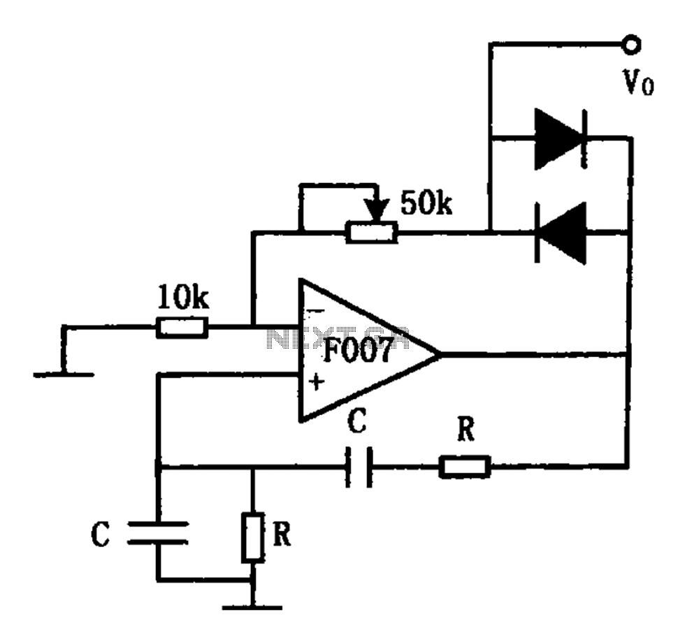
F007 stable sine wave oscillator circuit diagram
The stable sine wave oscillator circuit operates on the principle of negative feedback to regulate its output. The design typically consists of an amplifier stage where the gain is set to a level that allows for sustained oscillation. The circuit's stability is critical; thus, it is essential to maintain the loop gain within specific limits.
The two diodes in the circuit play a crucial role in the feedback mechanism. When the output voltage falls below a specific threshold, the reverse-biased diode effectively removes negative feedback, which allows the gain to increase and the output voltage to rise. This action continues until the output voltage exceeds the threshold, at which point the diode becomes forward-biased. This transition reduces the gain, leading to a decrease in output voltage, thereby creating a self-regulating oscillation cycle.
The potentiometer included in the circuit allows for fine-tuning of the output amplitude and distortion. By adjusting the resistance, the user can modify the feedback level, which directly impacts the output waveform's characteristics. This feature is particularly useful in applications requiring precise control over the output signal.
The frequency of oscillation is determined by the values of the resistor and capacitor in the circuit. The relationship is defined by the equation f0 = 1/(2πRC), where f0 represents the frequency of oscillation, R is the resistance, and C is the capacitance. By selecting appropriate values for R and C, the desired frequency can be achieved, making this circuit versatile for various applications in signal generation and waveform synthesis.
This stable sine wave oscillator circuit can be implemented in various electronic applications, such as audio signal generation, waveform shaping, and clock pulse generation. Its design ensures reliability and stability, making it suitable for both experimental and commercial use. As shown for the stable sine wave oscillator circuit. In order to obtain stable oscillation, the loop gain of claim 1. If the gain is too large, the waveform distortion; if the gain is too small, will appear to stop vibration. This circuit uses two diodes to stabilize oscillation. When the output voltage is too low, the diode is turned off, the negative feedback is cut off, the loop gain is increased, the output voltage is increased. When the output reaches a certain value, the diode is turned on, the loop gain is reduced. Output voltage decreases, and so forth, so that the output amplitude stability at a certain value. FIG potentiometer used to adjust the output amplitude and distortion. The oscillation frequency of the circuit is determined by the resistor R and the capacitor C, its size is:f0 1/2 RC.
Related Circuits
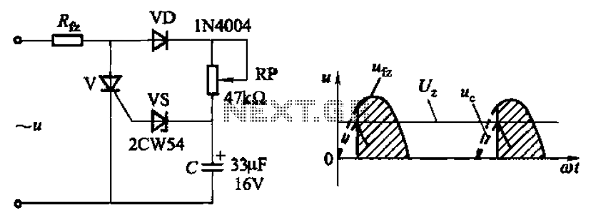
Circuit characteristics: A simple phase shift range of 180 degrees; exhibits good linearity and control accuracy compared to the first two options, making it suitable for low voltage applications, particularly in less demanding electroplating and electrolysis power supplies. The described...
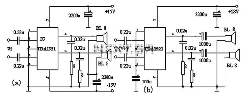
The TDA1521A amplifier circuit is designed for high-fidelity applications with minimal external components. It is suitable for powering Walkman devices or transforming low-powered computer speakers. The TDA1521A comes in a nine-pin single in-line plastic package and offers output power...
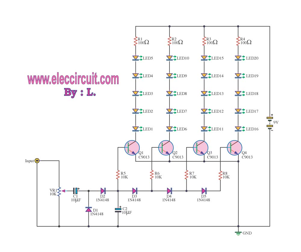
As a cyclist, there is a constant search for methods to enhance visibility during nighttime rides. The concept of the `NITE-RIDER` was developed to create a distinctive and attention-grabbing rear light for bicycles. This design features nine extra-bright LEDs...
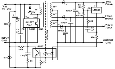
The following figure illustrates an example of a three-output flyback regulator constructed using the LM2577, which features electrical isolation between the input and output voltages. The circuit diagram specifies a voltage of 5V. Electrical isolation between the input and...
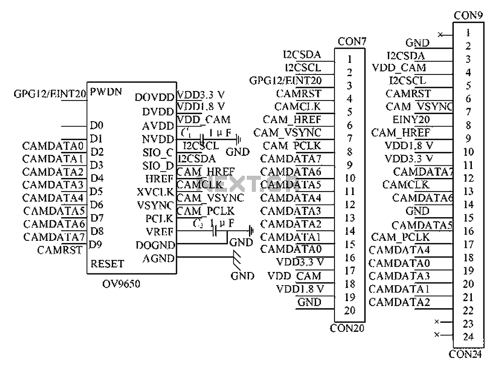
The circuit principle involves the OV9650 processor, which interfaces through three components: the SCCB interface, the data output interface, and the control interface. The SCCB interface is responsible for transferring initialization parameters from the processor's internal registers. It utilizes...
The VU meter operates in conjunction with the integrated amplifier circuit. The audio signal is processed by the audio amplifier circuit, which drives the VU meter to display the audio level. The VU meter circuit is designed to visually represent...