
Transistor Pulse Generator
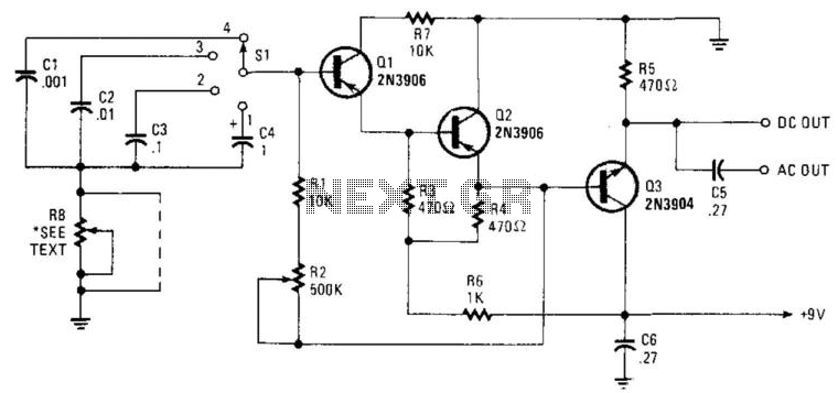
This circuit is designed to produce a series of narrow pulses with a frequency range from 2 Hz to 50 kHz, making it suitable for various applications such as timing, signal generation, and modulation. The core of the circuit relies on capacitors C1 through C4, which are configured to define different frequency ranges through a process known as decoding. This allows the circuit to produce distinct pulse frequencies by altering the charge and discharge cycles of these capacitors.
Resistors R1 and R2 play a crucial role in controlling the charging time of the capacitors. R1 is typically fixed, providing a baseline resistance, while R2 is a potentiometer that allows for fine-tuning of the frequency output. By adjusting R2, the user can manipulate the time constant of the RC (resistor-capacitor) network, thereby altering the frequency of the generated pulses.
Additionally, resistor R8 is included in the design to control the pulse width of the output signals. The pulse width can be varied between 7 ms and 10 ms, depending on the specific requirements of the application. In scenarios where precise pulse width is not critical, R8 can be omitted from the circuit to simplify the design and reduce component count without significantly affecting performance.
Overall, this circuit provides a versatile solution for generating narrow pulses across a wide frequency spectrum, with adjustable parameters to suit various electronic applications. Seven-V narrow pulses from 2 Hz to 50 kHz are produced by this circuit. CI through C4 provide frequency ranges i n decode steps. Rl and R2 control the charging time of CI through C4. R2 is a potentiometer used to set the frequency. R8 controls pulse width. Pulse width varies from 7 & to 10 ms. Depending on the frequency, R8 can be deleted if it is not needed. 🔗 External reference
Related Circuits
This is a straightforward sound effect generator based on the single sound generator chip UM3561. The UM3561 can produce four types of sound effects. Its basic operation involves generating a sound signal, which is then delivered to a 2N3706...
This circuit uses the Holtek HT2884 IC to produce 8 different sound effects. All sound effects are generated internally by the HT2884 IC. Power is a 3 Volt battery, but the IC will work with any voltage between 2.5...
The circuit illustrates a straightforward triangle and square wave generator utilizing a common dual operational amplifier, the LM1558, capable of producing very low frequencies around 10 kHz. The time interval for one half-cycle is approximately determined by the product...
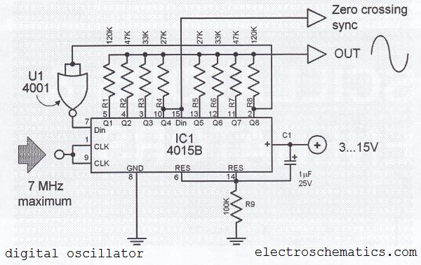
The digital sine wave generator (oscillator) circuit requires only a few components to produce signals with high amplitude constants and a wide range of variable frequencies. This circuit generates a sine wave signal, and by altering the values of...
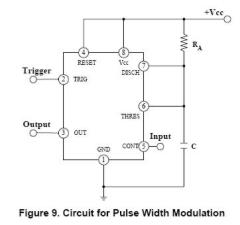
The circuit is effective for controlling the power supplied to devices such as fans, LEDs, or transformers and coils. By adjusting the pulse width, it is possible to control the speed of a fan without compromising torque. The IRF740...
This circuit generates a stable 1 kHz sine wave using an inverted Wien bridge configuration composed of components C1, R3, C2, and R4. It features a variable output, low distortion, and low output impedance to ensure good overload capability....