
Digital Sine Wave Generator Circuit
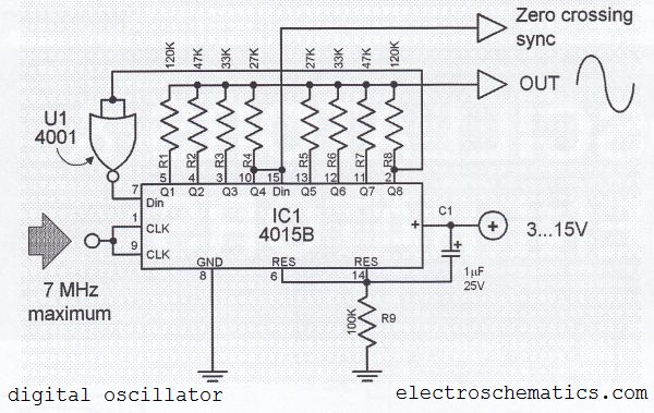
The digital sine wave generator circuit is designed to produce a sine wave output efficiently by utilizing a minimal number of components. At its core, the circuit employs a CMOS integrated circuit, specifically the 4015B, which is a dual 4-stage static shift register. The configuration of the resistors R1 and R8 allows for the adjustment of the waveform characteristics, enabling the generation of alternative signal forms such as triangular or square waves, depending on the application requirements.
Upon powering the circuit, the reset mechanism implemented through the resistor-capacitor combination of R9 and C1 ensures that all outputs of the 4015B are initialized to a known state (logic 0). This is crucial for the reliable operation of the circuit, preventing undefined states that could lead to erratic behavior.
The external clock signal serves as the timing reference for the oscillator. The relationship between the clock frequency and the output sine wave frequency is established such that the sine wave output is one-eighth of the clock frequency. This division is achieved through the internal logic of the 4015B, which effectively creates a frequency divider circuit.
The design also takes into account the limitations of the CMOS technology used. With a maximum operational frequency of 7 MHz for the CMOS ICs, the sine wave generator can achieve a peak output frequency of 500 kHz. This makes the circuit suitable for various applications, including signal processing, waveform generation, and testing scenarios where sine wave signals are required.
In summary, the digital sine wave generator circuit is a versatile and efficient solution for generating sine wave signals with high amplitude and variable frequencies, leveraging the capabilities of a CMOS integrated circuit while ensuring stability and reliability through careful component selection and configuration.The digital sine wave generator (oscillator) circuit has the advantage that only few components are needed to generate signals with high amplitude constants and variable within a very wide range of frequencies. The circuit shown here generates a sinewave signal. Other signal forms can also be generated by changing the values of R1 R8. After the power supply is connected to the circuit, the combination R9/C1 generates a short reset-pulse and all outputs if the 4015B are set to logic 0. The oscillator is controlled by an external clock. The frequency of the sinewave is 1/8 of the clock frequency. The highest frequency of CMOS ICs is 7 MHz, therefore a sine wave signal of 500 kHz maximum can be generated.
🔗 External reference
Related Circuits
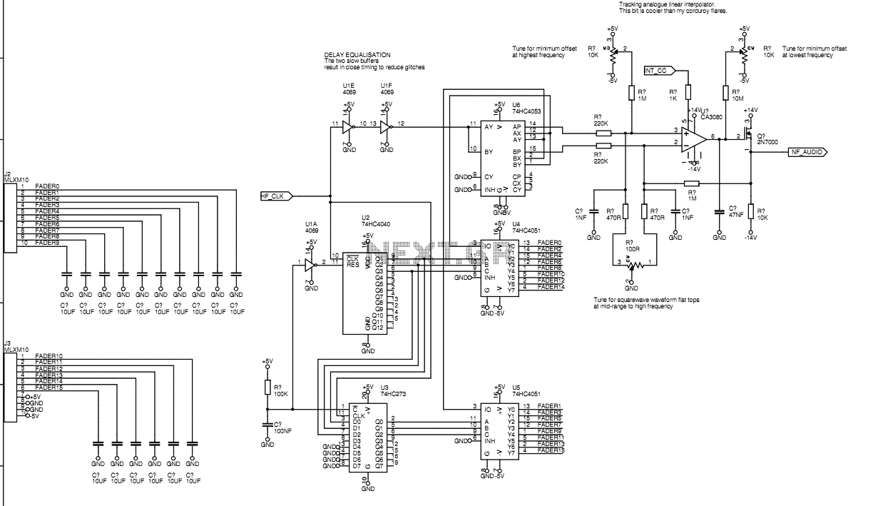
Originally I intended to have 32 faders. Once I tried fitting them on a veroboard, 32 seemed rather excessive so I have reduced to sixteen. This still allows generation of accurate eighth harmonic which compares well with the Hammond's...
The circuit flashes an LED when detecting an incoming call and is powered by a single 1.5V cell. It is designed to detect incoming calls in a cellular phone. This circuit utilizes a simple yet effective approach to alert users...

The demonstration circuit operates in the HM2007's manual mode. This mode uses a simple keypad and digital display to communicate with and program the HM2007 chip. When the circuit is turned on, the HM2007 checks the static RAM. If...
This circuit is designed to connect stereo outputs from four different sources or channels as inputs, allowing only one of them to be selected and connected to the output at any given time. When the power supply is turned...
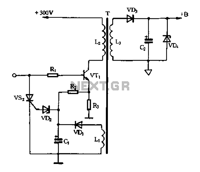
Color TV main power protection circuit The color TV main power protection circuit is designed to safeguard the television's power supply from various electrical anomalies, such as overvoltage, undervoltage, and short circuits. This circuit typically employs several components, including fuses,...
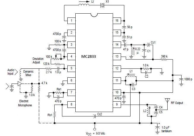
A simple FM transmitter circuit can be designed using the MC2833 integrated circuit, which is intended for cordless telephones and FM communication equipment. It features a microphone amplifier, a voltage-controlled oscillator, and two auxiliary transistors. The final output frequency...