
Binary circuit diagram box

The circuit utilizes an astable multivibrator, which is a type of oscillator that continuously switches between its high and low states without requiring any external triggering. The multivibrator generates a square wave output, which can be used to drive other components or systems. The frequency of oscillation is determined by the resistors and capacitors connected to the multivibrator.
In conjunction with the astable multivibrator, a flip-flop is employed to store the state of the output signal. The flip-flop can be configured to respond to the transitions of the multivibrator's output, effectively capturing the signal state at specific intervals. This capability allows for the retention of the signal's state even after the triggering event has passed, making it useful in applications where the state needs to be preserved for further processing or control.
The combination of the astable multivibrator and the flip-flop creates a robust circuit that can be utilized in various applications, such as timing circuits, pulse width modulation, or as a basic memory element in digital systems. The design flexibility allows for adjustments in frequency and output characteristics, making it suitable for a wide range of electronic projects. Proper selection of components and configuration will ensure optimal performance and reliability of the circuit. Circuit Description: This circuit uses an astable multivibrator to change the face-up or facing negative circumstances, also uses a flip-flop, flip-flop state that there had be en a change is to be stored by multivibrator complete cycle of each of the oscillator.
Related Circuits

Here is an updated schematic featuring the RF Solutions receiver along with several minor additions. The design includes additional circuitry to manage the signals effectively. The updated schematic incorporates an RF Solutions receiver, which is essential for receiving radio frequency...
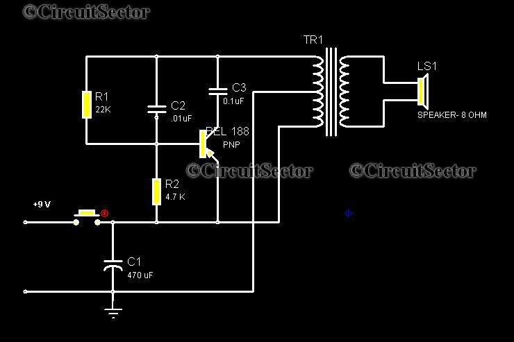
This circuit is a low-cost, one-touch doorbell using a Bel 188 transistor. It is likely one of the most economical bell circuits that can be constructed. The core component of this circuit is the output transformer from a push-pull...
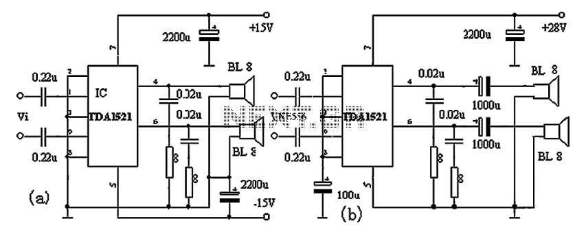
The TDA1521A amplifier circuit is designed for high-fidelity applications with minimal external components. It is suitable for powering Walkman devices or transforming low-powered computer speakers. The TDA1521A comes in a nine-pin single in-line plastic package and offers output power...

The automatic weapon features a magnetic switch circuit that is simple, reliable, has a low failure rate, and offers good versatility. It can be used to output performance or convert mechanical displacement. The circuit diagram utilizes a Hall switch...

The circuit utilizes six 12-volt lead-acid batteries to power the load. Three batteries are connected in series to generate 36 volts, while the other three are connected in parallel to maintain 12 volts. The total discharge current is 30...
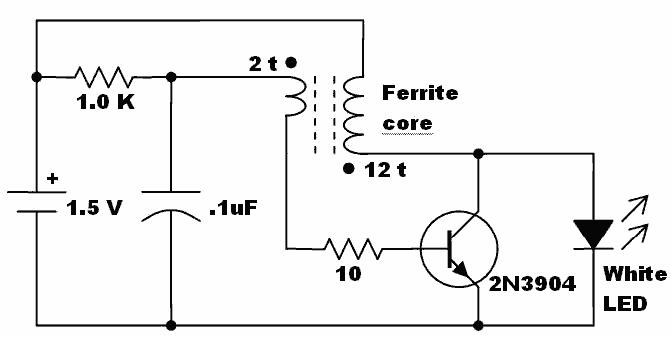
Here is an idea for a voltage booster that enables the lighting of a white LED using a single AA cell. This presents an opportunity to utilize one of the ferrite cores and white LED holiday lights mentioned in...