
Magneto Remote control switch circuit diagram

Adjusting RP1 and RP2 allows for sensitivity and reliability adjustments to prevent false triggering of VT. Figure 18-29b illustrates a magnetron device using a reed switch (KP). When the magnet is removed from KR, the KR contacts open, turning off the transistor and releasing relay KD. When the magnet approaches KP, KP contacts close, activating KD and controlling the electrical equipment in the control system circuit. Thus, the magnet's movement and position determine the device's operational status.
If the relay coil current for KD is small, or if the electrical equipment operates at low voltage and current, it can be directly connected in series with the reed switch, requiring fewer additional components. Reed contacts typically have a small capacity; therefore, to control larger loads, transistors, relay contacts, or thyristors must be used for voltage and current amplification. Since the thyristor gate voltage is low and requires minimal current, the reed switch must be connected to the thyristor control pole circuit, while the electrical equipment is connected to the thyristor's main circuit, providing an effective solution.
The magnetic switch circuit described operates on the principle of magnetic field detection using Hall effect sensors and reed switches. The Hall switch is sensitive to the presence of a magnetic field, allowing it to function as a trigger for other components in the circuit. The thyristor serves as a key component for controlling high-power devices, as it can handle larger currents and voltages compared to the reed switch.
The adjustable resistors RP1 and RP2 play a crucial role in tuning the circuit's sensitivity, allowing for customization based on the specific application requirements. This adaptability makes the circuit suitable for various applications, from simple mechanical switches to more complex automation systems.
In summary, this magnetic switch circuit combines simplicity and reliability with the ability to control larger electrical loads through the use of complementary components. The integration of Hall effect sensors and thyristors provides a robust solution for automatic weapon systems, enhancing their operational capabilities while maintaining ease of use and minimal maintenance requirements.Features automatic weapons such magnetic switch circuit is very simple, reliable, low failure rate, good versatility, can be used to output the performance or can be converted into mechanical displacement of the occasion. (2) is a circuit diagram using the Hall switch (SH) magnetron devices. When the magnet away from the Hall switch circuit, due to the positive effect of the fixed bias magnet, the Hall switch circuit is turned on, the output is low, the thyristor is turned off, AC contactor KM release.
While the magnet is moving into sensitive areas Hall switch when in the reverse magnetic field whose output suddenly promoted to the high level, by making the diode VD VT conduction, KM pull. Adjust RP1 and RP2, can take into account the sensitivity and reliable offerings (to prevent false triggering VT). Figure 18-29b is in magnetron device using reed (KP) is. When the magnet away from the KR, KR contacts open, transistor is turned off, the relay is KD released.
In the magnet close to the KP, KP contact closure, KD suction units, relay contacts KD string controlled electrical equipment control system circuit, so the movement of the magnet and its location determines the working status of the device. . (3) analysis of the circuit shown in circles 18-29, KD if the relay coil current is small, or low voltage electrical equipment, current is very small, it can be directly connected in series with the reed pipe, with less than other components.
Reed contacts generally small capacity, control large capacity of the load resistance, we must use transistors, relay embroidery, or the like contactor thyristor as voltage, current, or persuade amplifying. Since the thyristor gate voltage is low, current is very small, therefore, the reed switch connected to the thyristor control pole circuit required, electrical equipment connected to the thyristor main road in the pigsty, which is a better solution.
Related Circuits
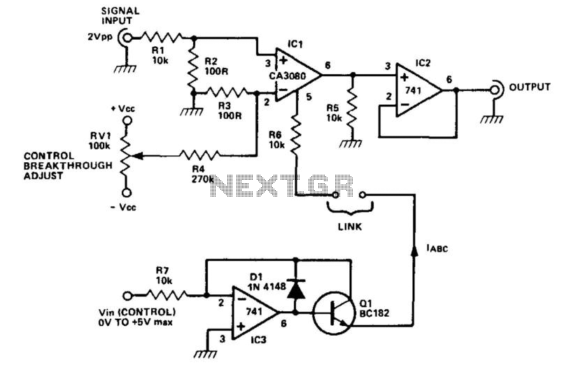
The CA3080 can be utilized as a gain-controlling device. The input signal is attenuated by resistors R1 and R2 so that a 20 mV peak-to-peak signal is applied to the input terminals. If this voltage exceeds a certain threshold,...
Turning electrical devices ON or OFF using a remote control is a well-established concept, with numerous devices available that perform this function effectively. To create such a device, it is necessary to construct a receiver and a transmitter, as...
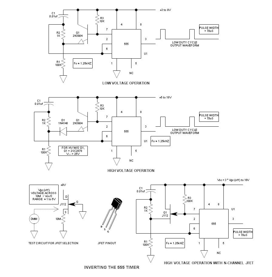
When using the 555 timer, the output polarity often appears to be incorrect, as the 555 typically cannot produce a duty cycle of less than 50%. This inverted 555 circuit is capable of generating duty cycles below 50%. The...
The primary motivation for utilizing battery power for trains is to eliminate the need for track cleaning and wiring. Track maintenance can pose significant challenges. Incorporating radio control into a battery-powered system enhances command control, an advantageous feature. In...

4 Channel 433MHz Wireless RF Remote Control Kit with a range of 200 meters. This RF remote control offers an extended range of up to 200 meters (650 feet) and is versatile for controlling various devices. The 4 Channel 433MHz...

The project described in this article is a constant Q, fully expandable graphic equaliser. Where most "conventional" graphic EQ circuits have a Q that is dependent on the setting of the pot, this one maintains the same Q at...