
FM demodulator circuit diagram 567

The FM demodulation circuit operates by converting frequency variations in the incoming FM signal into amplitude variations in the output signal. The input signal is fed into the circuit through pin 3, where it is processed to extract the original audio or information signal. The center frequency, fo, plays a crucial role in ensuring accurate demodulation, and it is set according to the formula fo = 1.1/RC, where R is the resistance and C is the capacitance in the circuit.
C1, the filter capacitor, is essential for smoothing out the output signal, minimizing high-frequency noise that could interfere with the clarity of the demodulated audio. C2, the bandwidth adjustment capacitor, allows for fine-tuning of the circuit's response to different frequencies. By adjusting C2, the bandwidth can be increased or decreased, affecting the circuit's sensitivity to adjacent channel interference. A smaller capacitance value for C2 results in a broader bandwidth, which can be beneficial in certain applications where signal strength is variable or where multiple signals are present.
In practical applications, the selection of C2 should be based on the specific requirements of the FM signal being demodulated, including the desired signal-to-noise ratio and the presence of adjacent channel signals. The design of the circuit must also consider the characteristics of the components used, as variations in component values can impact overall performance. The output from pin 5 delivers the demodulated signal, which can then be further processed or amplified for use in audio applications or data transmission systems. Proper layout and shielding of the circuit are also recommended to prevent interference and ensure optimal performance. As shown in Figure 567 FM demodulation circuit. The figure, the FM signal from the input pin 3, the demodulated signal output from 5 feet. FM demodulation circuit can signal ce nter frequency: fo 1.1/RC figure, C1 for the filter capacitor, C2 is the bandwidth adjustment capacitor C2 is reduced when, demodulates the bandwidth increases. C2 is selected on the basis of:
Related Circuits
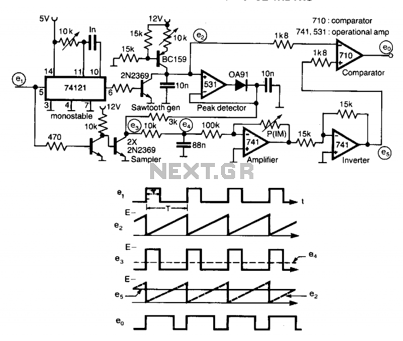
A circuit designed to multiply the width of incoming pulses by a factor that can be greater or less than unity is straightforward to construct. It features a single adjustable potentiometer for selecting the multiplying factor. This factor is...

The circuit is a high-power car audio amplifier schematic. It functions as a car audio amplifier using the PA02 and LH0101 integrated circuits (ICs). Each IC delivers an output power of 30W with an 8-ohm impedance. The part list...
This page is browser-friendly. To enhance readability, adjust your browser window to be narrower than the full screen. The page consists of two parts: the first part features a basic program demonstrating the RFID reader's functionality, while the second...
While developing an infrared (IR) extender circuit, a method was needed to measure the relative intensities of different infrared light sources. This circuit utilizes an SFH2030 photodiode as the infrared sensor. A CA3140 MOSFET operational amplifier is employed in...
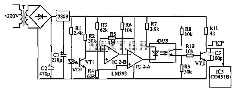
The circuit depicted in the figure operates as follows: when the phototransistor VT1 detects infrared light emitted by the infrared light-emitting diode, it enters a conductive state. This action causes the inverting input of comparator IC2-B, connected to pin...
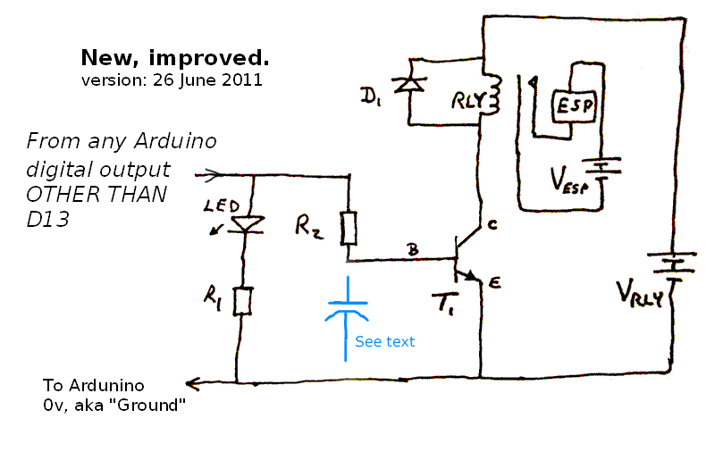
Due to the recent launch of Cranial Electrotherapy Stimulation (CES) portable devices in Europe, a similar circuit has been designed for hobbyists. CES is a widely used method for electrically enhancing brain function and has been prescribed by medical...