
Photoelectric counting circuit diagram

The described circuit functions as an object detection system utilizing infrared light transmission and reception. The primary components include an infrared light-emitting diode (VD1), a phototransistor (VT1), comparators (IC2-A and IC2-B), an optocoupler (4N35), and a secondary transistor (VT2) for signal processing.
Upon activation, the infrared LED emits light that is continuously monitored by the phototransistor. The circuit is designed to detect interruptions in the infrared beam caused by physical objects passing between the emitter and the receiver. When the beam is unobstructed, the phototransistor remains conductive, maintaining a low output at the comparator IC2-A, which keeps the optocoupler and VT2 activated.
The logic of the circuit relies on the behavior of the comparators, which compare input voltages and determine the output state based on the presence or absence of infrared light. The transition from low to high output at the collector of VT2 serves as a pulse signal, which is essential for counting events (i.e., the passing of objects). This pulse signal can be processed further by a decimal counter, which accumulates counts and sends the data to a display circuit for visual representation.
In summary, the circuit effectively monitors the presence of objects using infrared technology, allowing for applications in automation, counting systems, or security monitoring. The design emphasizes reliability and responsiveness, making it suitable for various electronic applications that require object detection and counting. Circuit shown in Figure, when the phototransistor VT1 receives infrared light-emitting diode to the infrared light emitted, VT1 conduction, the inverting input of the comparato r IC2-B 6 feet low end, 7 feet high output, applied to the comparator IC2-a inverting input terminal, so that a pin output low, the optocoupler LEDs light 4N35 within the corresponding photodiode is turned on, the transistor VT2 are conduction, VT2 collector output low. When an object passes between the infrared light-emitting diodes VD1 and receiver tube VT1, infrared rays are blocked, VT1 off, 1 foot high output of IC2-A, 4N35 off, VT2 off, VT2 collector output high, so when there is when an object by VT1, VT2 collector output on it counted pulse signal which is sent to a decimal counter, then sent decoding display circuit, showing corresponding data.
Related Circuits
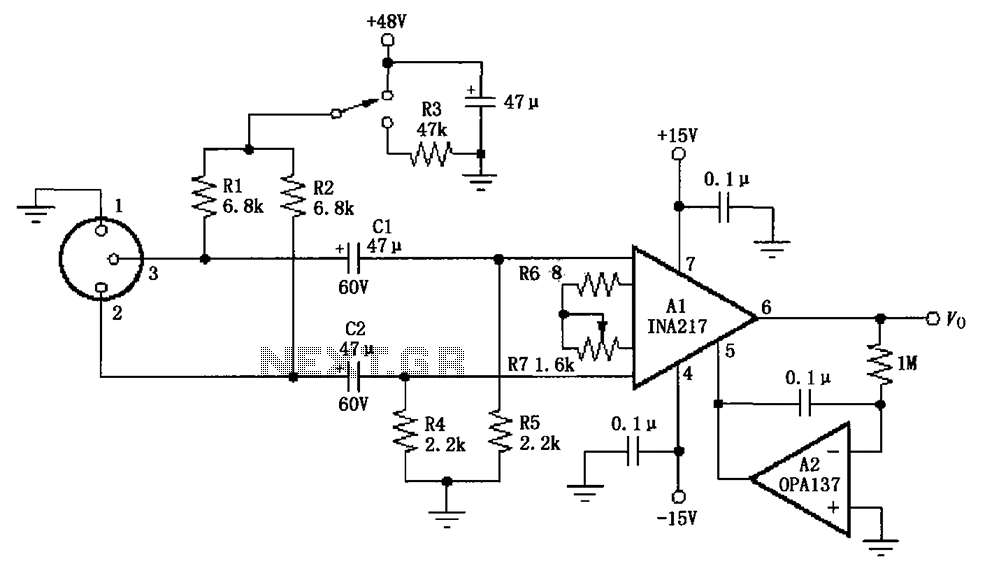
The circuit depicted in the figure consists of an INA217 professional miniature microphone preamplifier. A switch is included to select the use of phantom power. When the switch is connected to +48V, phantom power is enabled; if the switch...
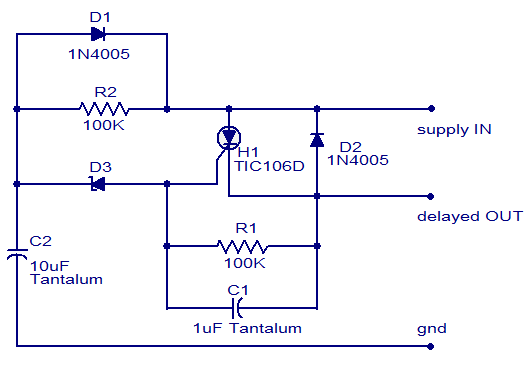
The circuit diagram presented is of a straightforward DC power delay circuit utilizing a silicon-controlled rectifier (SCR). This circuit is quite useful and can be applied in various scenarios. The operation of this circuit is uncomplicated. Upon the application...

It is a wireless doorbell with a cost of about $10.00. This product encourages a shift in approach to building projects, utilizing such items to learn about their functions and modify them to meet specific needs. The doorbell incorporates...
At this voltage regulator prototype the maximum current, with output shortcircuited it was only 0.5 A, so no overheating occurred. In this DC voltage regulator circuit, T1 is for current limitation. As soon as the voltage on the R2...
This circuit is designed to indicate, via a flashing LED, when room noise exceeds a predetermined threshold, selectable from three fixed levels: 50 dB, 70 dB, and 85 dB. The circuit utilizes two operational amplifiers to amplify the sound...
The circuit operates on the principle that insects, such as mosquitoes, can be repelled using sound frequencies in the ultrasonic range (above 20 kHz). It utilizes a Phase-Locked Loop (PLL) integrated circuit, specifically the CMOS 4047, configured as an...