
Touch Switch
The circuit employs a combination of transistors and passive components to create a functional electronic system, which can be utilized in various applications, particularly in amplification and switching circuits.
The MPF102 serves as the primary JFET (Junction Field-Effect Transistor) for high-frequency amplification in UHF/VHF ranges, making it suitable for radio frequency applications. It can be substituted with NTE451 or ECG451, ensuring flexibility in component sourcing while maintaining performance specifications.
The 2N3565 transistors (Q2 and Q3) are utilized for signal amplification and can be replaced with other common NPN transistors such as 2N2222(A), BC107, BC108, or BC109(A/B/C). These alternatives provide similar characteristics, allowing for easy replacement in case of unavailability while ensuring the circuit's functionality remains intact.
The TIP31 (Q4) is employed as a power transistor, providing the necessary current amplification. It can be replaced with NTE196 or ECG196, both of which are comparable in terms of specifications and widely available, ensuring that the circuit can be easily maintained or repaired.
The resistors (R1 to R7) are critical in setting the biasing conditions and gain of the transistors. R1, with a resistance of 22 MΩ, serves as a high-value resistor for input impedance. R2, at 47 kΩ, and R3, R4, both at 100 kΩ, are used for feedback and biasing, while R5, R6, and R7, each at 2.2 kΩ, help stabilize the operating point of the transistors.
The capacitors C1 and C2, both rated at 22 µF and 25V, are used for coupling and decoupling purposes, ensuring that AC signals pass through while blocking DC levels, thereby maintaining the integrity of the signal processing within the circuit.
The circuit also incorporates a touch plate, which can be made from any non-corrosive material; a silver quarter is suggested for its conductive properties. This touch plate can trigger the circuit, providing an interface for user interaction.
For output indication, a #53 bulb (La1) can be used, though it is noted that a small relay could serve as an alternative, offering additional flexibility in output control.
Overall, this circuit design is versatile, allowing for various component substitutions while maintaining performance and functionality across different applications.The MPF102 (Q1) can be replaced with a NTE451 or ECG451, but still widely available. JFET-N-CHAN, UHF/VHF AMP. The 2N3565 (Q1/Q2) can be replace with a 2N2222(A), BC107, BC108, BC109(A/B/C), NTE123A, or ECG123A. The TIP31 (Q3) can be replaced with a NTE196 or ECG196, but is a common type and widely available. The 'Touch Plate' can be anything non corrosive. I use a silver quarter. You can also use a small relay instead of the #53 bulb. R1 22Meg resistor R2 47K resistor R3,R4 100K resistor R5,R6,R7 2K2 resistor C1 Capacitor, 22?F, 25V C2 Capacitor, 22?F, 25V Q1 MPF102 Q2,Q3 2N3565 Q4 TIP31 La1 Bulb, #53 🔗 External reference
Related Circuits
This circuit is an ultra-sensitive infrared (IR) receiver designed to control various AC devices via an IR transmitter. It utilizes a phototransistor... The ultra-sensitive IR receiver circuit is engineered to detect infrared signals emitted from an IR transmitter, enabling the...
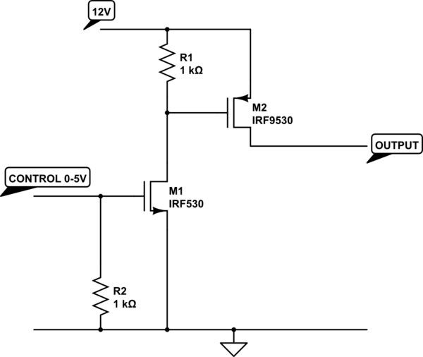
The transistor depicted is a P-channel MOSFET functioning as a high-side switch. Typically, an N-channel MOSFET is preferred for low-side switching, but the P-channel variant can be utilized effectively with the addition of a load at the drain. When...
This circuit is designed around a 555 timer and utilizes very few components. Its simplicity allows even novices to construct and use it as a control device. A laser pointer, widely available in the market, can be employed to...
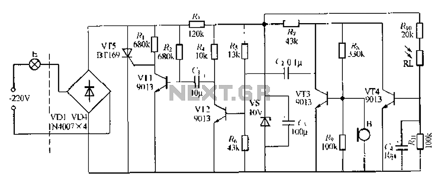
This circuit describes a sound and light control delay system for a walkway stairs light switch. It involves various components including 220V AC electric bulbs, diodes (VD1-VD4), and resistors. The circuit utilizes a rectifier regulator to stabilize the voltage...
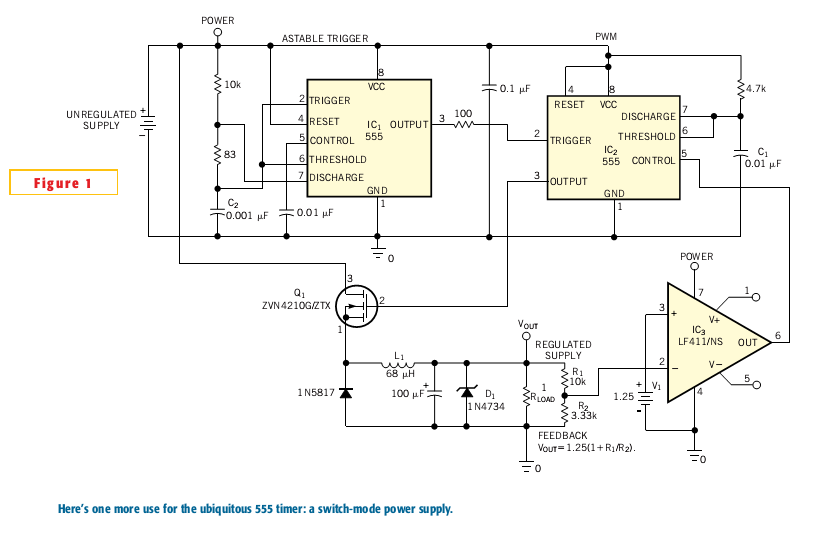
Most switch-mode power supplies utilize a PWM (pulse-width-modulated) output that is regulated through voltage feedback. A 555-timer IC can be used to generate PWM at a low cost. The circuit diagram illustrates how to convert a 555 PWM circuit...
This is an ultrasonic motion detector circuit with high movement sensitivity. It can detect even minor air movements, such as hot air rising or wind blowing, when the trimpot is adjusted to a sensitive position. The transmitter emits a...