
Outdoor Garden LED Solar Light Circuit

The Outdoor LED Solar Garden Lights circuit operates on the principle of solar energy conversion and light detection. The solar panel collects sunlight during the day and converts it into electrical energy, which is stored in the SLA battery. The use of a diode (D9) ensures that the battery does not discharge back into the solar panel at night. The LM555 timer IC is a versatile component in this circuit, configured to function as a comparator that detects the voltage level from the LDR. When the ambient light falls below a certain threshold, the LM555 output switches, allowing current to flow through transistor T1, which in turn energizes the LED string.
The trimpot (P1) allows for fine-tuning of the light sensitivity, enabling the circuit to be adjusted for various light conditions. This feature is particularly useful for ensuring optimal operation in different geographical locations or during varying seasons. The LED string (D1-D8) is designed to provide sufficient illumination for garden areas, ensuring visibility and aesthetic appeal at night. Resistors (R1-R8) are critical for current limiting, preventing the LEDs from drawing excessive current that could lead to overheating or premature failure.
The choice of a transparent plastic enclosure serves both functional and aesthetic purposes, allowing the solar panel to receive maximum sunlight while protecting the electronic components from environmental factors. Proper mounting of the LDR is essential for accurate light sensing; it should be positioned to avoid direct sunlight to ensure it only responds to ambient light levels.
This project is an excellent example of renewable energy utilization and can serve as a foundation for further experimentation and development in solar-powered lighting solutions. Modifications such as adding additional LED strings or integrating more advanced sensors can enhance functionality and performance, catering to the needs of hobbyists and engineers alike.This Outdoor LED Solar Garden Lights project is a hobby circuit of an automatic garden light using a LDR and 6V/5W solar panel. During day time, the internal rechargeable 6 Volt SLA battery receives charging current from the connected solar panel through polariy protection diode D9 and current limiting resistor R10.
If ambient light is normal, tra nsistor T1 is reverse biased by IC1 (LM555). Here IC1 is wired as a medium current inverting line driver, switched by an encapsulated light detector (10mm LDR). Multi-turn trimpot P1 sets the detection sensitivity. When ambient light dims, transistor T1 turns on to drive the white LED string (D1-D8). Now this lamp load at the output of T1 energises. Resistors R1-R8 limits the operating current of the LEDs. When the ambient light level restores, circuit returns to its idle state and light(s) switched off by the circuit.
Assemble the Outdoor Solar Lights circuit on a general purpose PCB and enclose the whole assembly in a transparent plastic box. Drill suitable holes on the top of the encloure to mount the mini solar panel (SP1) and the light sensor (LDR), and in front for fitting power switch (S1) and the sensitivity controller (P1).
Fix the battery inside the cabinet using a double-sided glue tape/pad. Finally, the LDR should not be mounted to receive direct sunlight. It must be mounted at the top of the enclosure, pointing to the sky say southwards. This circuit is very simple. So interested and experienced hobbyists can alter/modify the whole circuit as per their own ideas without any difficulty (Just try a 6V relay with T1 to drive more number of LED strings) 🔗 External reference
Related Circuits
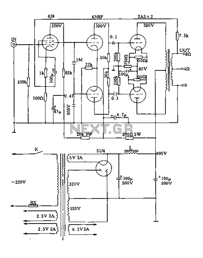
FIG. 2A3A is a low direct thermal resistance transistor with a resistance of only 800 ohms. The output transformer has a primary screen to load impedance of 3.5k ohms. The push-pull amplifier tube operates with a screen voltage ranging...
As with any audio mixer circuit, a slight loss is always introduced. The final summing amplifier has a gain of 2 or 6dB to overcome this. The input line level should be around 200mV RMS. The mic inputs are...
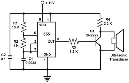
The circuit utilizes a 555 timer integrated circuit (IC) configured as an astable multivibrator, which generates a continuous signal at a specific frequency as long as its reset pin (pin 4) is held high. The ultrasonic transducer employed in...
The ICs LM4651 and LM4652 are types of MOSFET integrated circuits and power amplifiers that include high-efficiency amplifiers, making them suitable for self-powered speakers, subwoofers, and high-quality car audio systems. The LM4651 is a fully integrated conventional pulse width...
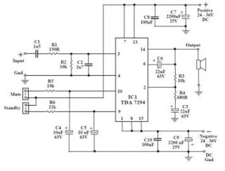
This audio amplifier circuit utilizes the TDA7294, a power integrated circuit designed for high-quality audio applications. The TDA7294 operates as a class AB amplifier, characterized by low noise and distortion levels, a wide bandwidth, and robust output current capability....
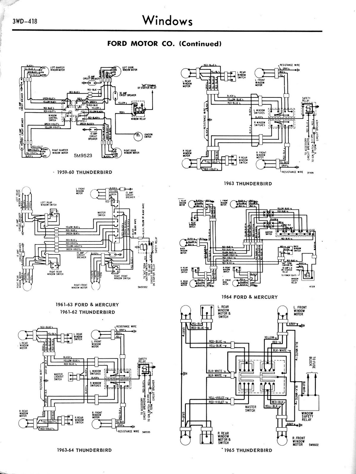
Toyota MR2 Exterior Lights Wiring Diagram Manual PDF Download. The Toyota MR2 Exterior Lights Wiring Diagram Manual provides a comprehensive guide for understanding the wiring configurations associated with the exterior lighting system of the Toyota MR2 model. This manual is...