
Over-voltage protection circuit

The described circuit employs a silicon-controlled rectifier (SCR) to manage the operation of a relay in response to voltage changes in a 12-V power supply line. The SCR is strategically placed in parallel with the voltage line to monitor the voltage levels effectively. Its gate terminal is connected to a voltage divider or sensing circuit that includes a resistor, R1, which sets the trigger point for the SCR. This configuration ensures that the SCR remains in an off state while the voltage stays below 12 V, thereby maintaining the closed state of relay K1 and enabling current to flow to the connected load.
When the voltage exceeds the predetermined threshold of 12 V, the current flowing through R1 becomes sufficiently high to trigger the SCR. This transition causes the SCR to enter a conductive state, effectively short-circuiting the relay coil and opening the contacts of K1. Consequently, the load is disconnected from the power supply, preventing potential overvoltage conditions that could damage the load.
The choice of R1 is critical as it determines the sensitivity of the SCR to voltage changes. Adjusting R1 allows for fine-tuning the voltage level at which the SCR will trigger, providing flexibility in the circuit's operational parameters. This design is particularly useful in applications where overvoltage protection is needed, ensuring that sensitive devices are safeguarded against voltage spikes.
In summary, this circuit exemplifies a simple yet effective method for controlling power delivery to a load based on voltage levels, using a silicon-controlled rectifier in conjunction with a relay to provide reliable operation and protection.A silicon-controlled rectifier is installed in parallel with the 12-V line and connected to a normally-closed 12-V relay, K1. The SCR's gate circuit is used to sample the applied voltage. As long as the applied voltage stays below a given value, SCR1 remains off and Kl's contacts remain closed, thereby supplying power to the load.
When the source voltage rises above 12 V, sufficient current is applied to the gate of SCR1 to trigger it into conduction. The trigger point of SCR1 is dependent on the setting of R1. Once SCR1 is triggered (activating the relay), K1's contacts open, halting current flow to the load.
Related Circuits
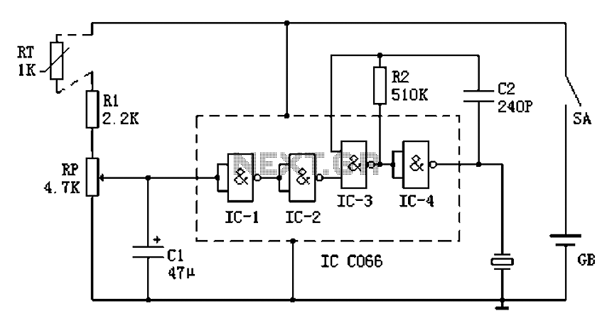
Boiling water on a kitchen gas stove can lead to issues such as spilling boiling water if the process is not monitored, which can extinguish the flame and cause gas leakage. A notification device can address this problem. The...
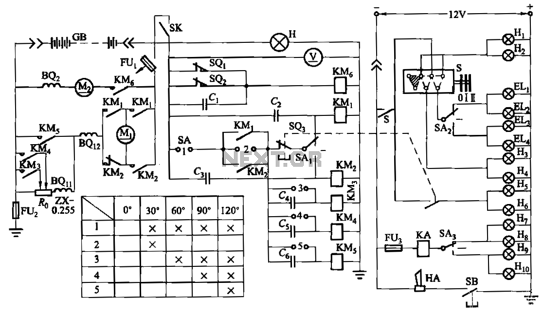
The forklift electric drive system comprises two DC series motors and associated control equipment. A 4.5 kW electric motor drives the vehicle through a mechanical transmission mechanism, enabling forward and backward movement of the forklift. A 6 kW pump...

A VU (Volume Unit) meter has traditionally been a key component of audio metering systems. The Peak Program Meter (PPM) is known for its inadequacy in accurately displaying peak signal levels. This circuit serves the same function as previously...
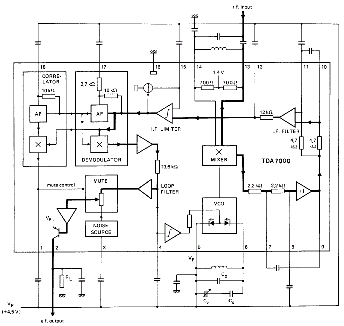
GENERAL DESCRIPTION The TDA7000 is a monolithic integrated circuit designed for mono FM portable radios or receivers, emphasizing minimal peripheral components to achieve compact dimensions and reduced costs. This integrated circuit features a Frequency-Locked-Loop (FLL) system with an intermediate...
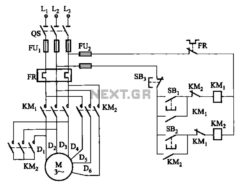
The circuit illustrated in Figure 3-97 features two contacts and is designed specifically for a 2kW dual-speed motor. In this configuration, SB1 is utilized for low-speed operation, while SB2 serves as the high-speed run button. The circuit operates by allowing...
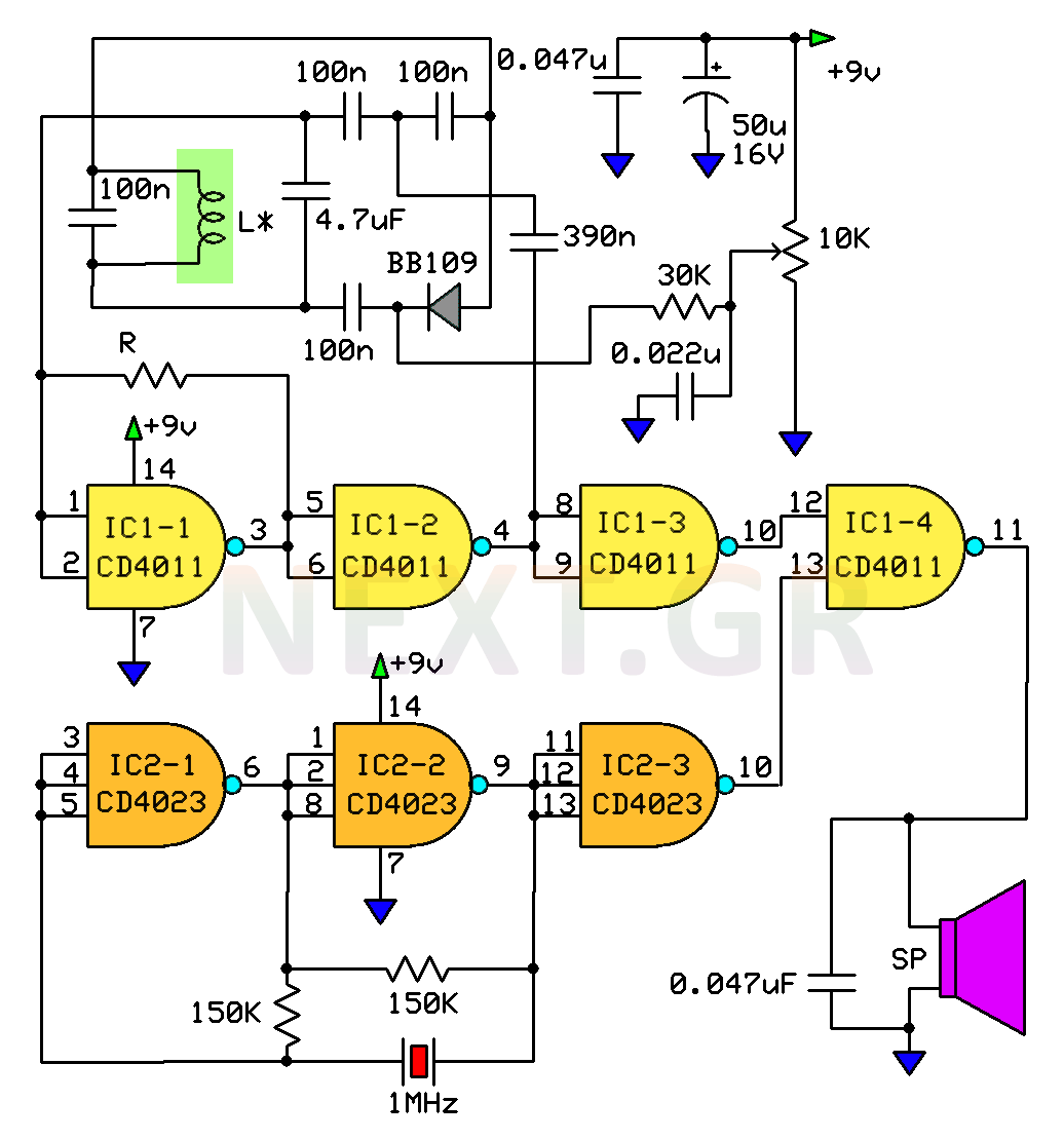
This circuit is a metal detector designed to detect large metallic objects at depths ranging from 2 to 3 meters, depending on the size of the object and the type of soil. The construction is straightforward, making it accessible...