
Overload protection circuit diagram of 25 ohm speaker

The overload protection circuit is a critical component in audio systems, ensuring that speakers are safeguarded against excessive power levels that could lead to damage. This circuit operates at a power rating of 650 mW and is designed to function with a 12 V power supply. The speaker connected to this circuit has an impedance of 25 ohms, which is a common specification for many audio applications.
The circuit utilizes a series of transistors to monitor the current flowing to the speaker. The specifications of the transistors used are as follows: VT1 is a NB111EH/J transistor, which serves as the primary control element. It is responsible for detecting overload conditions and initiating protective measures. VT2, designated as NR001E, acts as an additional control element that assists in the switching operation, enhancing the responsiveness of the circuit under overload conditions.
Transistors VT3 and VT4, identified as NA11EB/J and NA12EB/J respectively, function as output drivers. They are designed to handle the current required by the speaker while also providing a fail-safe mechanism that disconnects the speaker from the power source in case of an overload. This arrangement not only protects the speaker but also ensures the longevity of the entire audio system.
In summary, the overload protection circuit is an essential feature in audio equipment, designed to prevent damage to speakers by utilizing a series of transistors that monitor and control the power delivered to the load. Proper selection of components, such as the specified transistors, is crucial for ensuring effective operation and reliability of the circuit. As shown in overload protection circuit power 650mW, supply voltage 12V, speaker 25 ohms. Part Component Specifications: VT1: transistor NB111EH/J VT2: Transistors: NR001E VT3: transistor NA11EB/J VT4: transistor NA12EB/J
Related Circuits
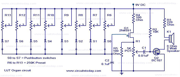
A UJT organ circuit with a circuit diagram is explained in detail. A 2N4891 UJT is used for the operation of the circuit. The UJT (Uni-Junction Transistor) organ circuit is designed to utilize the unique characteristics of the 2N4891 UJT...
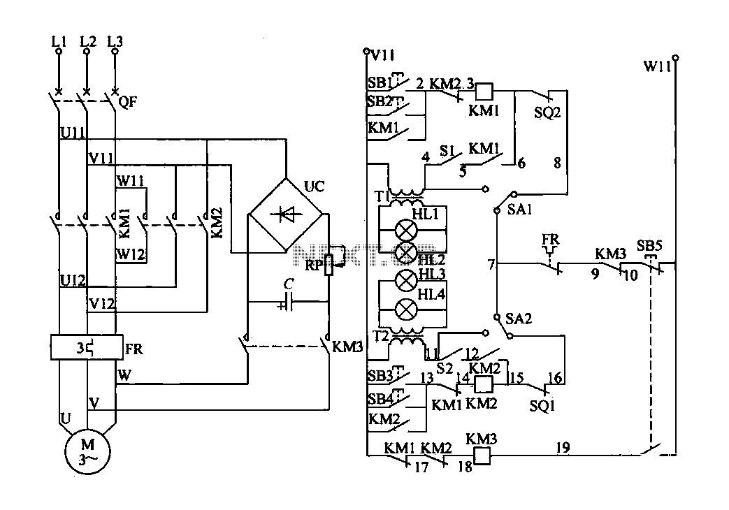
The electric valve control circuit consists of three main parts: the main lines, control lines, and power consumption brake line. The main circuit includes a power switch (QF), three-phase AC contactors (KM1, KM2), a thermal relay (FR), and a...
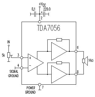
This TDA7056 power audio amplifier circuit diagram project is designed to deliver a maximum output power of 1 watt into an 8-ohm load when powered by a 6-volt supply, or a maximum output power of 3 watts into a...
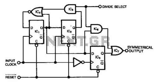
This circuit generates a symmetrical waveform by dividing the input frequency by either 2 or 3. The Divide Select input governs the division factor. When the Divide Select input is high, flip-flops IC1 and IC2, along with the associated...
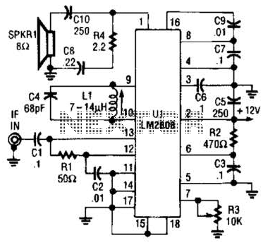
An LM2808 performs IF amplification of the 4.5-MHz sound subcarrier, limiting, detection, and audio amplification. If the center frequency must be changed, then change L1/C4. Audio output is 0.5 W. R3 is the volume control. The LM2808 is an integrated...
This timer was designed primarily to switch off a portable radio after a set period. This feature allows users to fall asleep on the beach or in a hammock, knowing that the receiver will automatically turn off after a...