
TDA7056 audio amplifier circuit diagram electronic project

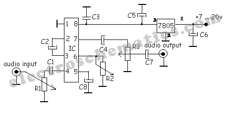
The TDA7056 is a low-voltage audio amplifier IC that is commonly used in portable audio applications due to its compact size and efficiency. The circuit typically includes the TDA7056 IC, which is the core component responsible for amplification. The input signal is fed into the IC, and the output is taken across the load, which can be a speaker or similar audio device.
To construct this audio amplifier, two capacitors are used for coupling and decoupling purposes. The first capacitor is typically placed at the input to block any DC offset from the audio source, ensuring that only the AC audio signal is amplified. The second capacitor is used at the output to filter out any unwanted high-frequency noise, providing a cleaner audio signal to the speaker.
The resistor in the circuit is usually employed to set the gain of the amplifier, allowing for adjustment of the output volume. The choice of resistor value will affect the overall performance of the amplifier, including its gain and distortion characteristics.
The TDA7056 is designed to operate efficiently without the need for a heatsink, making it suitable for battery-powered devices where space and weight are critical considerations. This feature simplifies the design and assembly process, allowing for a more compact and lightweight audio amplifier solution.
Overall, this circuit is ideal for hobbyists and engineers looking to create a simple yet effective audio amplification solution for various applications, such as portable speakers, radios, and other audio devices.This TDA7056 power audio amplifier electronic circuit diagram project will provide a maximum output power of 1 watt into a 8 ohms load using a 6 volts power supply, or a maximum output power of 3 watts into a 16 ohms load using a 11 volts power supply. As you can see in the circuit diagram you will need just two capacitors and one resistor to co nstruct this audio amplifier. The TDA IC don`t need to be mounted on a heatsink. 🔗 External reference
Related Circuits
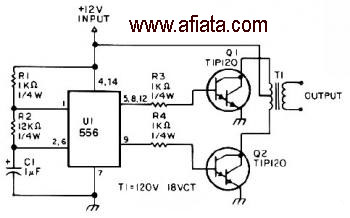
The first section of the 555 timer is configured as an astable oscillator, with R2 and C1 determining the frequency. The output is accessible at pin 5. The second section functions as a phase inverter, with its output available...
A simple audio compressor is designed using the SSM2165 integrated circuit (IC). There is limited explanation available regarding the schematic of this compressor circuit; however, special attention should be given to the capacitor used. The audio compressor circuit utilizing the...

This design circuit serves as a converter utilizing the LM2623A ratio adaptive circuit to drive a digital camera motor. It generates 5 volts from input voltages that range between 1.8 and 4.5 volts. The circuit's duty cycle, while not...
There was difficulty in understanding that the Source pin connects to low voltage (source of electrons) and the Drain pin connects to high voltage (absorbs electrons). This concept is fundamental to basic electricity, but it required some time to...
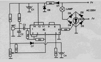
This 220 Volt disco lamp circuit is not a voice switch (VOX), as it cannot differentiate between musical sounds and human voices. Instead, it functions as a sound-activated device. An interesting application of this circuit is to control the...
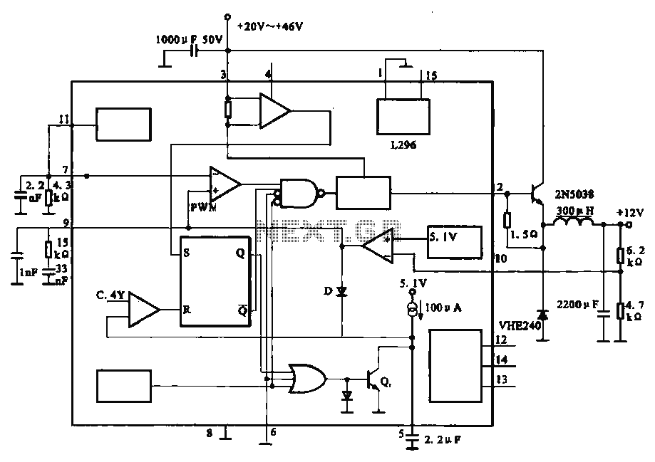
The circuit outputs 12V at 10A and utilizes a high-current switching power supply design based on the L296 component. This configuration allows for an output current of up to 10A, and the entire circuit is compact with minimal component...