
Collection of Crystal Oscillators
The circuits described utilize 3rd and 5th overtone crystals, specifically designed for frequencies ranging from 15 to 65 MHz and 60 to 105 MHz, respectively. These crystals operate in their series resonant mode, which is crucial for maintaining stability and accuracy in frequency generation. When the crystal is short-circuited, the oscillator is expected to function at or near the desired frequency, indicating that the circuit is properly designed.
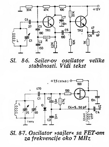
In the operational phase, the inductor L1 plays a vital role in frequency tuning. It must be adjusted to achieve either a minimum voltage across the crystal or to precisely match the desired operating frequency. The ideal scenario is for these two tuning points to coincide; however, manufacturing tolerances often introduce discrepancies that necessitate careful adjustment and verification of the output frequency.
It is critical to avoid including a tuned circuit at the crystal overtone frequency within the collector circuit of transistor TR1. Such a configuration can lead to oscillations that are not controlled by the crystal, undermining the circuit's stability. Instead, a tuned circuit may be added at a frequency that is twice or three times that of the crystal, allowing for the extraction of harmonics from the collector, which can be beneficial for certain applications.
Transistor selection is also a key consideration in the design of these circuits. High DC gain (HFE) transistors with low base resistance (RBB) are recommended to ensure efficient operation. Additionally, the transit frequency of the chosen transistors should be at least ten times greater than the oscillator frequency to maintain performance and prevent distortion.
The circuits can accommodate various overtone crystals, with 3rd overtone crystals typically supplied for frequencies between 21 and 60 MHz, while 5th overtone crystals are available for frequencies ranging from 60 to 126 MHz and 7th overtone crystals for frequencies from 126 to 175 MHz. This flexibility allows for a wide range of applications in frequency generation and signal processing.On following pages circuits are shown for 3rd overtone crystals 15 to 65MHz and 5th overtone crystals 60 to 105 MHz operating in their series resonant mode. In both of these circuits with the crystal short circuited, the oscillator should operate at or near the required frequency.
With the crystal in circuit L1 should be adjusted for either (a) minimum voltage across the crystal or (b) for the exact frequency required. Ideally, these two points would coincide but they rarely will due to the need for a manufacturing tolerance on crystal frequency.
If L1 is of incorrect size it is possible for the oscillator to operate on a different order of overtone, for this reason it is important to accurately check the output frequency. Under no circumstances should a tuned circuit at the crystal overtone frequency be included in the collector circuit of TR1 as this configuration will result in oscillation not controlled by the crystal. However it is possible to include a tuned circuit at that point which is twice or three times the crystal frequency.
It is then possible to extract from the collector the harmonics of the crystal frequency. It is recommended that transistors for use in this circuit have a high DC gain (HFE) and a low base resistance (RBB). Also ensure that the transit frequency is at least ten times that of the oscillator frequency. Unless otherwise specified we supply 3rd overtone crystals between 21 and 60 MHz. 5th overtone between 60 and 126 MHz and 7th between 126 and 175 MHz. 🔗 External reference
Related Circuits
Will an LC-based oscillator be able to demonstrate performance comparable to crystals under such conditions (possibly in unusual configurations like LC-opamp) so that any energy loss at each stage is recovered, resulting in a narrower bandwidth? Examine some amateur...
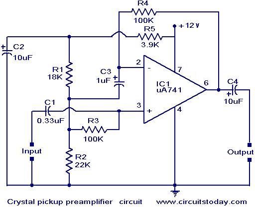
A preamplifier that operates on a single supply and is suitable for high-impedance crystal pickups is presented here. The circuit functions as a non-inverting AC amplifier, with the gain determined by the feedback resistor R4; a smaller R4 results...
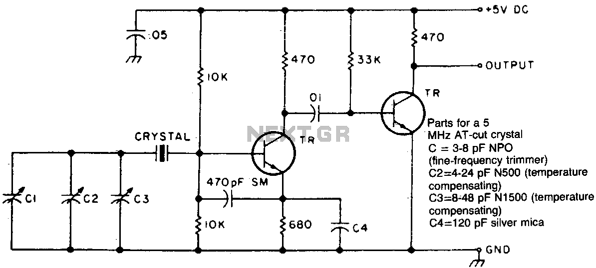
Two different negative-coefficient capacitors are blended to produce the desired change in capacitance to counteract or compensate for the decrease in frequency of the "normal" AT-cut characteristics. The circuit utilizes a combination of two negative-coefficient capacitors to achieve a specific...
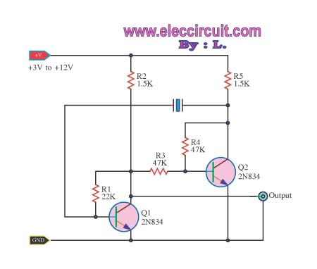
Features: 1. The operating voltage is low, functioning with a single supply of 2.0V. 2. Power consumption is minimal, with a supply current of 5 µA at 32 kHz and 130 µA at 1 MHz. 3. It has a...
An oscillator circuit of this nature is often utilized as a clock circuit. This circuit employs a crystal frequency control with a stability of one million hertz. An oscillator circuit designed for clock applications typically generates a periodic signal, which...
The AM signal is captured by the antenna, 10 mt long horizontal wire, WELL insulated from earth. The inductor and capacitor form a resonator, that will tune with the station whose frequency is F = 1 / (2 *...