
Parachute Recovery System

The described parachute recovery system for rockets utilizes a combination of mechanical and electrical components to ensure successful deployment. The core of the system is the air-speed switch, which is designed to activate the ejection charge for the parachute at a specific moment during the rocket's ascent. This switch consists of a spring-loaded vane that reacts to changes in aerodynamic drag as the rocket decelerates. The design ensures that as the rocket approaches its peak altitude, the reduction in speed allows the vane to return to its neutral position, thereby closing the electrical circuit and triggering the ejection charge.
The ejection charge itself is a self-contained unit, separate from the rocket's main engine. It is electrically ignited and is designed to deploy the parachute at a controlled rate, minimizing the risk of tearing due to high-speed deployment. The integration of a backup timer serves to enhance reliability, particularly in scenarios where the rocket may not slow down sufficiently due to a horizontal velocity component. This timer introduces a delay, allowing the rocket to decelerate further before the parachute is deployed, thus improving the chances of a safe recovery.
The overall effectiveness of the system relies on careful calibration of the air-speed switch and the timing mechanism, ensuring that both components work harmoniously under various flight conditions. Despite the challenges faced in circuit design, the combination of mechanical and electronic elements in this recovery system represents a significant advancement in amateur rocketry, showcasing the importance of iterative design and testing in the development of reliable aerospace systems.Before I began building amateur rockets, I built and flew model rockets, starting in the summer of 1971. Looking for a greater challenge, the following year I decided to begin building my own rockets, entirely from scratch.
Although my first rocket was a simple one, not equipped with a parachute, I was soon working on my second, and larger rocket, which I wanted to recover by parachute. It seemed natural, therefore, to base the parachute recovery system for this rocket on a concept that was similar to that used for model rockets, specifically, the concept of using an "ejection charge" with a time delay, to deploy the parachute. Unlike model rockets, however, I used an ejection charge that was entirely separate from the engine, a self-contained unit containing a small charge that was electrically ignited.
Instead of a time delay, I utilized a pendulum switch, similar to the method I read about in the book "The Amateur Scientist", which was based on the naive notion that, as the rocket would "turn over" at the peak of the trajectory, the pendulum would fall over, closing the switch contacts. Needless to say, if the parachute did successfully eject during these early flights, it did so almost immediately after engine burnout.
Thinking that the pendulum was simply too sensitive to angle, I tried a mercury switch, which needless to say, led to the same futile results. It wasn`t until I began to understand the concept of free-body motion and the consequences of aerodynamic drag, that I realized that such a method is doomed to failure.
Any such inertial type of switch will close immediately after burnout, as the rocket begins to decelerate at a rate greater than that due to gravity alone, as a consequence of drag. The pendulum, mercury, or any other inertial mass, however, decelerates at a rate dictated by gravity alone, thus moving forward relative to the rocket body to which the switch is attached, thereby closing the switch contacts.
By this point in time, I had developed a reasonably effective method for ejecting, or deploying, the parachute from the rocket (even at high speed, a benefit from the trials and tribulations experienced !), and it was simply a matter of ejecting it at a slow enough speed such that it was not torn off immediately! The solution seemed to be an air-speed switch, that is, a switch with a spring-loaded external flap or vane that would deflect due to aerodynamic drag.
As the rocket would slow down near the peak, the spring would return the vane to the undeflected position, closing an electrical switch. This would then trigger the parachute ejection charge. This method proved to be, after several design iterations, quite successful. The eventual design incorporated a backup timer, in case the rocket veered significantly from vertical during ascent, and would consequently not slow sufficiently to close the air-speed switch (due to horizontal component of velocity).
As well, to help overcome this possible problem, the air-speed switch was put in series with a short delay timer (2-3 seconds), which would allow for a higher speed setting of the air-speed switch. The short delay would allow the rocket to slow further before triggering parachute ejection. The goal of developing a highly reliable parachute recovery system was never fully achieved. Although the method developed for ejecting the parachute from the rocket was very reliable, as was the air-speed switch for sensing the point in trajectory when the parachute should be released, the problem with reliability laid in designing an electrical circuit for linking these two actions.
In hindsight, it does not seem like a difficult problem, and any difficulties were likely a result of trying to be too fancy in the circuit design. And besides, electronics never were my greatest expertise ! After engine burnout, a rocket continually slows down as it ascends skyward, succumbing to the effects of gravit
🔗 External reference
Related Circuits
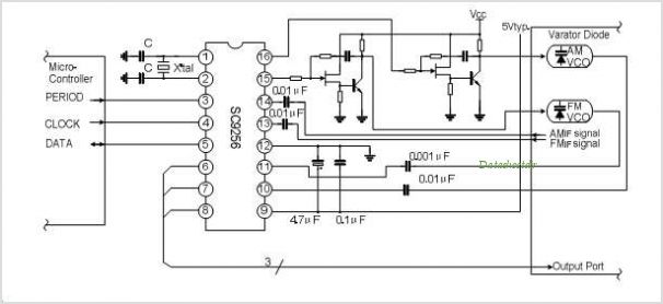
The SC9270C/SC9270D is a comprehensive DTMF receiver that integrates both bandsplit filtering and digital decoding functions. The filter section utilizes switched capacitor techniques to achieve high- and low-group filtering along with dial-tone rejection. The decoder employs digital counting techniques...

When the supply voltage drops below a minimum threshold, it is often advisable to disconnect the supply from the system to prevent poor performance or erratic operation. The circuit presented achieves this with minimal cost, board space, and complexity....
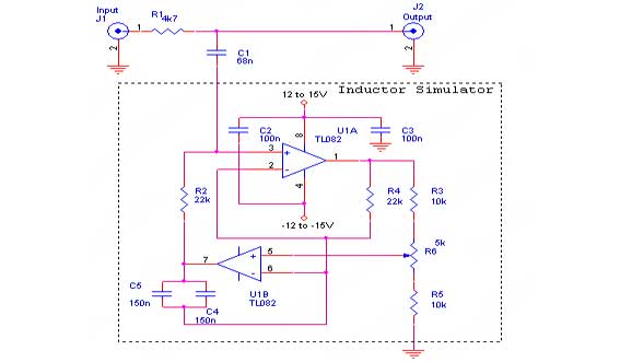
The hum noise is produced by an electronic device with improper design. To address this issue, it is essential to identify the source of the hum. This involves checking the grounding, cabling, casing, and other factors that may contribute...
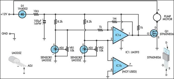
This circuit optimizes the operation of a solar hot water system. When the water in the solar collector is hotter than the storage tank, the pump runs. The circuit comprises two LM335Z temperature sensors, a comparator, and a MOSFET....
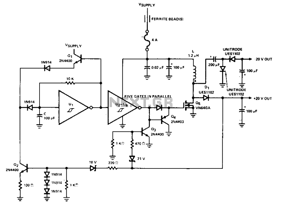
This PWM control circuit generates control pulses for the DMOS power switch in the flyback circuit. The PWM output produces a pulse width that is proportional to the input control voltage, with the repetition rate governed by an external...
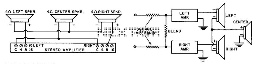
A straightforward technique for obtaining a center or third channel without the need for an additional transformer or amplifier. Four speakers are connected to eight amplifier taps, while eight and sixteen speakers are connected to sixteen taps. By blending...