
Switching inverter for 12v systems

The PWM control circuit is a critical component in managing the operation of the DMOS power switch within a flyback converter. The circuit utilizes a pulse-width modulation technique to regulate the power delivered to the load. The width of the PWM output pulse is directly influenced by the input control voltage, allowing for precise control over the energy transferred to the output.
The external clock signal is essential for defining the frequency of the PWM operation, which in turn dictates how often the DMOS switch is turned on and off. The frequency selection is crucial for optimizing the performance of the flyback converter, as it affects both the efficiency and the response time of the circuit.
The inclusion of an error amplifier is vital for maintaining the desired output voltage level. This component continuously monitors the output voltage and compares it to a predetermined reference voltage. Any discrepancy between the two values generates an error signal, which is then fed back to the PWM controller. This feedback mechanism ensures that the output voltage remains stable even as the load conditions change, effectively compensating for variations in load demand.
The reference voltage serves as a benchmark for the error amplifier, determining the target output voltage for the circuit. By adjusting the control voltage based on the feedback from the error amplifier, the circuit can dynamically respond to changes in load, maintaining performance and preventing issues such as voltage spikes or drops.
In summary, this PWM control circuit exemplifies a robust design that integrates control, feedback, and stability mechanisms to efficiently manage the operation of a DMOS power switch in a flyback converter application. The synergy between the PWM output, error amplifier, and reference voltage forms a comprehensive control system akin to that found in servo mechanisms, ensuring reliable and effective power management.This PWM control circuit provides the control pulse to the DMOS Power Switch in the flyback circuit. The output of the PWM is a pulse whose width is proportional to the input control voltage and whose repetition rate is determined by an external clock signal. To provide the control input to the PWM and to prevent the output voltage from soaring or sagging as the load changes the error amplifier and reference voltage complete the design.
They act as the feedback loop in this control circuit much like that of a servo control system.
Related Circuits
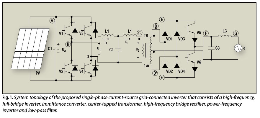
The electric utility grid-connected photovoltaic (PV) system is a significant technology for future renewable energy applications. The electric utility grid-connected photovoltaic (PV) system plays a crucial role in the advancement of renewable energy technologies. This system integrates solar panels into...
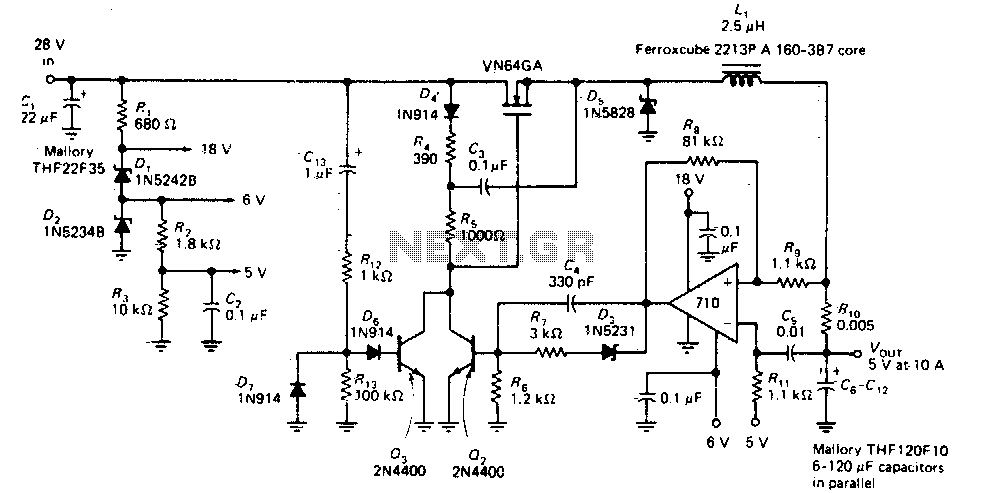
This circuit provides a regulated DC output with less than 100 mV of ripple for microprocessor applications. The required operating voltages are derived from a bleeder resistor network connected across the unregulated 28 V supply. The output of the...
Using this circuit you can convert the 12V dc into the 220V AC. In this circuit, 4047 is used to generate the square wave of 50Hz and amplify the current and then amplify the voltage by using the step...
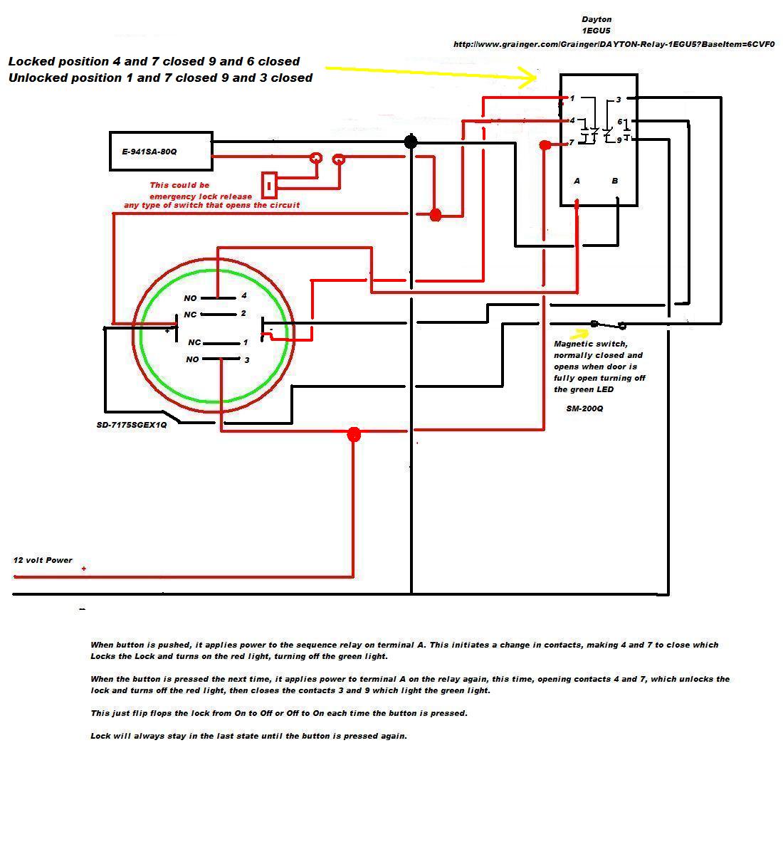
A 12V DC electromagnetic lock is designed with a push-to-lock and push-to-unlock mechanism using an existing LED indicator/switch. The switch should display a green light when unlocked and red when locked. The LED indicator/switch is the SD-7175SGEX1Q, which is...
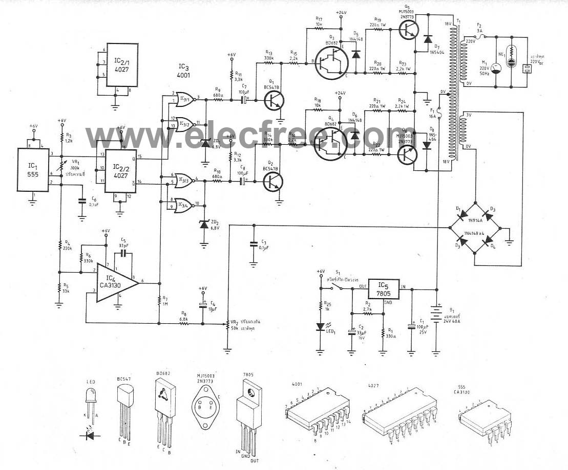
This circuit is a 300W inverter power converter, which takes a 24V input battery and outputs 220V AC at 50Hz with a maximum power of 300W. The main components used in this circuit include the IC CD4027, NE555, CA3130,...
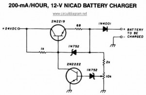
This NiCAD battery charger circuit charges the battery at 75 mA until it is fully charged, after which it reduces the current to a trickle rate. It can completely recharge a dead or unpowered battery in 4 hours, and...