
Parallel port provides high-resolution temperature sensing

A simple Turbo C program running in DOS mode effects the data-transfer cycle in the PC, whereas the transfer is automatic in the chip upon reception of SCK. The routine reads a low byte and a signed high byte and creates a floating-point value by simply adding the low byte, divided by 256, to the high byte. In the highest resolution mode, which this design uses, a data read can occur only every 1.2 sec, and timing loops should be adjusted accordingly. The settling time, DELTIME, may also need adjustment depending on the speed of the PC used. The sample program prints the bytes transferred as well as the temperature, and it can be easily modified. The data sheet explains the use of the configuration register and changes to make if a higher data rate with lower resolution is required. The data transfer begins with the write of an address byte to the chip's SDI in the order A7 to A0 (high bit to low bit). If A7 is high, a write takes place; otherwise, a read occurs. For a write, D7 to D0 route to the chip's SDI. For a read, D7 to D0 are available on the chip's SDO. The program uses both SDI and SDO and ignores whichever it doesn’t need. For example, data goes to the chip's SDI even during a read, but the chip ignores this data. Each byte transfers as 8 bits, and each transfer involves the following steps: The PC raises D1/SCK and places 0 or 1 on D2 for the chip's SDI. The PC then reads PAPER. Finally, the PC drops D1/SCK.
The DS1722 digital thermometer is designed for integration into various electronic systems where precise temperature measurement is essential. It operates within a temperature range of –55°C to +120°C, making it suitable for both low and high-temperature applications. The device's resolution of 0.0625°C allows for fine measurements, while its maximum accuracy of 2°C can be enhanced through calibration, providing flexibility for various use cases.
In terms of interfacing, the DS1722 can operate using either a three-wire interface or an SPI interface, which is advantageous for compatibility with different microcontrollers and systems. The choice of connection through a DB-25 connector to the PC's parallel port allows for straightforward integration into existing systems, especially those utilizing older hardware setups.
The device's low power consumption of 0.5 mA ensures that it can be powered directly from the parallel port, eliminating the need for additional power sources and simplifying the overall circuit design. The SPI mode of operation, with the SCK signal provided by the PC, allows for flexible timing management during data transfer, which can be crucial in applications where timing precision is necessary.
The accompanying software routine developed in Turbo C facilitates the interaction with the DS1722, managing the data transfer process and enabling the user to read temperature values effectively. The program’s structure allows for easy modifications to accommodate various application requirements, such as adjusting the data rate or resolution. The detailed operation of the data transfer process, including the handling of address and data bytes, ensures reliable communication between the PC and the thermometer.
Overall, the DS1722 digital thermometer presents a versatile and efficient solution for temperature measurement in electronic applications, with a well-defined interface and software support that enhances its usability in both simple and complex systems.The Dallas Semiconductor (www.dalsemi.com) DS1722 digital thermometer allows measurement resolution as fine as 0.0625°C in digital form and with linear response. The accuracy specification is only 2°C, but you can improve this figure by careful calibration. Moreover, the accuracy spec is unimportant in applications in which you measure only changes in temperature or in which you must closely maintain a noncritical temperature.
The measurement range is –55 to +120°C, the part can use either three-wire or SPI interface, and the cost is approximately $1. The eight-pin part is available in SO or µSOP packaging and in large quantities as a flip-chip measuring only about 1 mm sq.
In this application, the chip attaches directly to the PC's parallel port through a male DB-25 connector. Because the device draws a maximum of 0.5 mA, the port can supply the power, and its supply range tolerates variations in voltage levels that may exist on varying ports.
The chip is in SPI mode with the SCK clock signal supplied by the PC; in this way, data-transfer timing is noncritical.
A simple Turbo C program (Listing 1) running in DOS mode effects the data-transfer cycle in the PC, whereas the transfer is automatic in the chip upon reception of SCK. The routine reads a low byte and a signed high byte and creates a floating-point value by simply adding the low byte, divided by 256, to the high byte.
In the highest resolution mode, which this design uses, a data read can occur only every 1.2 sec, and you should adjust the timing loops accordingly. You may also need to adjust the settling time, DELTIME, depending on the speed of the PC you use. The sample program prints the bytes transferred as well as the temperature, and you can easily modify it.
The data sheet explains the use of the configuration register and changes to make if you need a higher data rate with lower resolution. Click here to download Listing 1. The data transfer takes place beginning with the write of an address byte to the chip's SDI in the order A7 to A0 (high bit to low bit).
If A7 is high, a write takes place; otherwise, a read occurs. For a write, D7 to D0 route to the chip's SDI. For a read, D7 to D0 are available on the chip's SDO. The program always uses both SDI and SDO and ignores whichever it doesn't need. For example, data goes to the chip's SDI even during a read, but the chip ignores this data. Each byte transfers as 8 bits, and each transfer involves the following steps: The PC raises D1/SCK and places 0 or 1 on D2 for the chip's SDI. The PC then reads PAPER. Finally, the PC drops D1/SCK.
Related Circuits
The target of this project was the design of a small portable mixer supplied by a 9V PP3 battery, keeping high quality performance. The mixer is formed assembling three main modules that can be varied in number and/or disposition...
This receiver is designed around the widely used ZN414 integrated circuit (IC) and operates within the AM band, covering frequencies from 550 to 1600 KHz. To utilize the receiver for Longwave frequencies, it is necessary to replace the coil...
When running large-scale software or games, a computer's internal temperature can increase significantly, especially during hot summer months. Although the machine is equipped with a CPU and graphics card fan, poor hot air circulation prevents immediate removal of heat...

AVR has two different programming modes called Parallel Programming Mode (Parallel Mode) and Serial Downloading Mode (ISP mode). In Parallel Mode, the programming is done using multiple data lines simultaneously, allowing for faster programming speeds. This mode is typically...
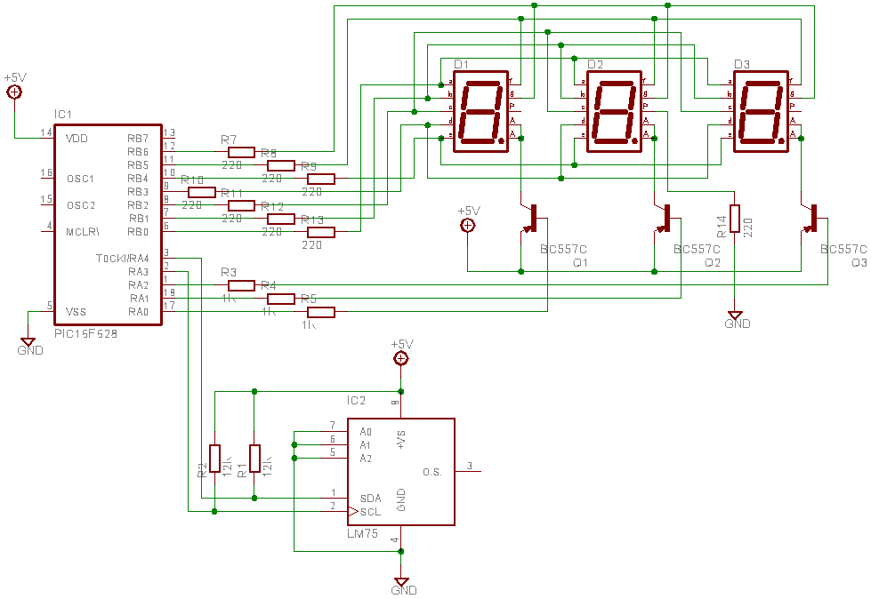
This is a test project assembled quickly on a solderless breadboard. It utilizes an LM75 temperature sensor to read the current temperature through the I2C communication protocol and displays the result. The project employs the LM75, a digital temperature sensor...
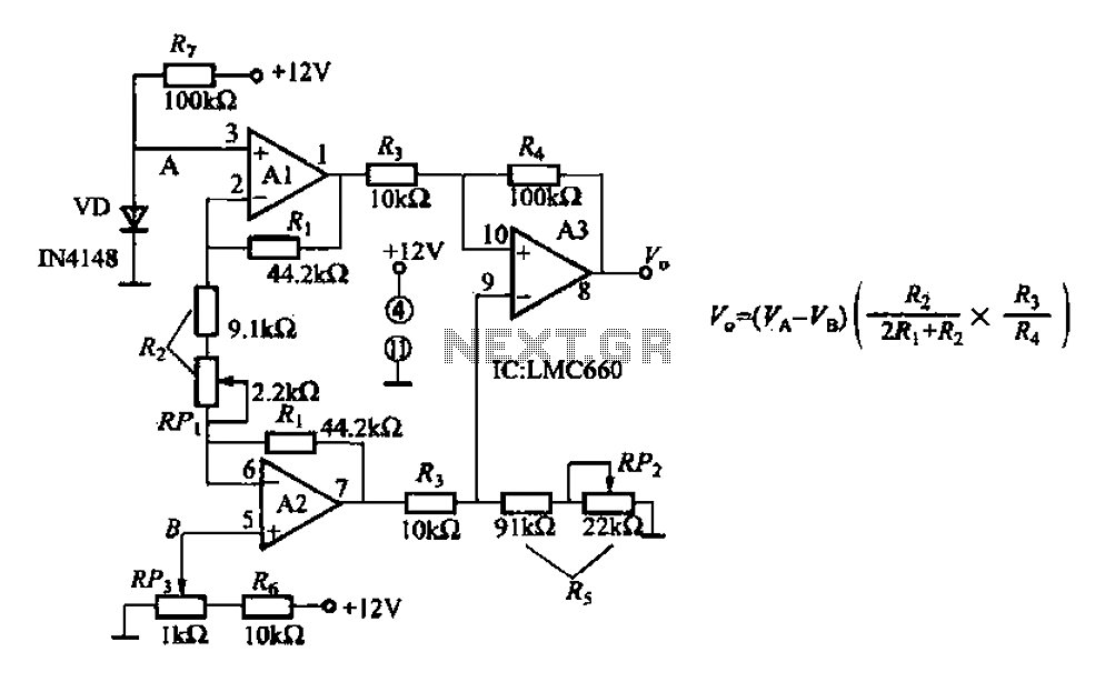
A diode IN4148 temperature circuit is presented. The circuit operates within a temperature range of -25 to 125 degrees Celsius, with an accuracy of 0.5. The core components of the operational amplifier circuit consist of four LMC660 amplifiers. It...