
Parking aid

The circuit utilizes a microcontroller as the central processing unit, which executes the programmed logic for distance measurement and sound signal generation. The infrared sensors detect reflected light from nearby obstacles, converting this information into a digital signal that the microcontroller processes. The microcontroller's firmware includes algorithms for interpreting the sensor data, determining the distance to the nearest obstacle, and adjusting the sound output accordingly.
The audio feedback system is designed to provide clear and distinct alerts to the driver, ensuring that the user is aware of their proximity to potential hazards. The use of varying frequencies and beep lengths serves to communicate different levels of urgency effectively. The design also incorporates safety features, such as the soft ticking sound when no obstacles are detected, which indicates that the system is operational and ready for use.
The choice of the Sharp IR distance sensor GP2D02 is critical for the functionality of the circuit, as it offers a reliable means of measuring distances within the specified range. The sensor's triangular measurement principle allows for accurate readings, and the additional signal processing enhances the effective range of the system.
In terms of construction, attention to waterproofing and proper sensor orientation is essential to ensure consistent performance in various environmental conditions. The integration of aluminum foil as a grounding shield is a noteworthy enhancement that mitigates interference and improves the accuracy of the readings. The overall design emphasizes simplicity in wiring and installation, making it accessible for users looking to implement a parking aid system in their vehicles.This circuit is based around the PIC 16C84 (or PIC 16F84) microcontroller. This chip is actually a small computer contained in a single chip, including RAM memory, EEPROM, I/O ports, CPU and so on. When you buy this chip, it comes empty with no program on it. You have to compile the source code and download the resulting machine code into it, usin g a PC and a small programmer attached to the parallel port of the PC and the chip. To get yourself familiar with this stuff, I suggest you first read this link: Getting started with microcontrollers. This circuit is a parking aid. Two infrared sensors (or at least one) are continuously sensing the distance between the back of your car and an obstacle (i.
e. the other car). Feedback to the driver is given via sound through a speaker. There are six levels: the first level (starting level) sounds short low frequency beeps and long pauses to indicate that there is an obstacle further than about 1m40. The second level sounds long low frequency beeps when you are between 1m and 1m40 of the obstacle. The third, fourth and fifth level will get you higher in frequency (and shorter beeps) when you are nearing the other vehicle at resp.
less than 1m, 75 cm and 50 cm. When you are closer than 25 cm, you are in level 6 where quick dual-tone sounds can be heared, indicating that you are about to crash. When there is no obstacle, no sound is heard except some soft ticking, indicating that the processor is running OK.
When the device is put on (preferably through a switch or operated together with the back driving lights) a short dual tone is heard to confirm that the device is up and running. The circuit makes use of the Sharp IR distance sensor GP2D02. This sensor is based on triangular measuring principles, and is designed to measures distances between 10 cm and 80 cm, but using some smart interpreting of the digital output value, we can get in practice a range of more than 140 cm.
If you want to use only one sensor, you should replace the line "#define TWO_SENSORS" with "#define ONE_SENSOR" in the source code. Otherwise the software would hang because it can`t find the second sensor. The complete device consists of three units: two outdoor units (one of which contains the microprocessor, power supply, first sensor and some other components, the other one contains only the second sensor) and one indoor unit, which is basically just an audio amplifier with speaker and power supply.
There are only three wires necessary to connect the outdoor unit at the back of the car to the indoor unit close to the driver. If you use two sensors, you need four wires from the second sensor to the first sensor. When using two sensors, the software will allways take the highest value of the two sensors for conversion to sound signals (this is the shortest distance).
The LCD output in the source code is only used if you run this software on the `LCD Experimental board using PIC16F84` shown elsewhere on this site, not for this circuit. In this case, the output value of the sensor (or the highest output value of the two sensors) will be shown constantly on the LCD display.
The two (or one) outdoor units should be build completely waterproof. I used a plastic housing with a hole, where I mounted a piece of glass to put the sensor behind. You get the best results when you mount the sensors vertically, with the IR light emitting diode upwards. It is advisable that you use shielded cable between the two outdoor units not longer than 1. 4 meter. I experienced that winding a peace of aluminium folio around the sensor and connecting this folio to ground, gave much better results.
When the sensor is pointing to open air, it should give a reading of 1. Without the folio, the reading will vary randomly between 1 and 40. So when using the folio, we can start beeping at a much lower value, giving a higher range. 🔗 External reference
Related Circuits
This sensor circuit was designed to assist in parking a car near a garage wall while reversing. LED D7 lights up when the distance from the bumper to the wall is approximately 20 cm. LEDs D7 and D6 illuminate...
An RC car has been developed that can autonomously identify a parking space and execute parallel parking maneuvers. The car navigates along a street using a distance sensor to locate potential parking spaces on its right. Upon identifying a...
Convert the smart cards into manual push buttons to control energy consumption, alleviating the consumer's concern about sourcing smart cards, especially given the limited supply in the area. The proposed modification involves replacing the current smart card system with...
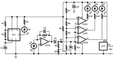
This circuit was designed to assist in parking a car near a garage wall while reversing. LED D7 lights up when the distance to the wall is approximately 20 cm. When the distance reduces to about 10 cm, both...
The circuit generates geomagnetic fields that allow for their perception, creating an ideal environment for sound sleep. When SW2 is open (Alternate mode operation), the device operates for a pre-set duration and then pauses for the same amount of...
A USBI2C can be utilized with each sensor, allowing for a configuration of four sensors at a cost of £120. The SRF02 operates on the I2C bus, which should not be extended beyond approximately 2 meters. The proposed solution...