
Passive Audio Mixer

This simple line mixer has two drawbacks: it attenuates the signal all the time (even sliders set to maximum) and the output impedance is quite high. The first problem can be solved by just turning a little more volume in the amplifier. High output impedance is not a problem when connected to high impedance amplifier input with short wires (few meters). The dual logarithmic potentiometers are mechanically connected so that they move together, ensuring synchronized volume adjustments for left and right channels. This mechanical connection is achieved using dual potentiometers. If separate linear potentiometers are used, the sliders can be linked together through an appropriate method. For those preferring independent volume controls for each channel, separate potentiometers can be utilized without mechanical linkage.
The circuit allows for flexibility in connector types; 1/4" phone jacks can be used instead of RCA jacks without issues, provided they are wired correctly. Each input consists of two connections: for RCA connectors, the outer part connects to the common ground, while the center connects to the resistor. For phone jacks, the body connects to the common ground, and the tip connects to the resistor.
The schematic of the mixer circuit illustrates that the potentiometer sliders within the dual potentiometers are interconnected by a single line. Each input and output pin corresponds with a ground signal on the right side of the signal line. This design ensures a straightforward yet effective solution for mixing audio signals in various applications, particularly where portability and simplicity are key considerations.I designed this circuit for one friend of mine to be used as a small portable DJ mixer. The circuit is an audio mixer circuit so simple as it can be. There are two dual logarithmic potentiometers in the circuit to adjust the input signal levels and some resistors to do the actual mixing. The circuit is totally passive, so no power supply is needed. The circuit is suitable to be uses as a mixer between two line level sources and one HIFI amplifier input.
This circuit have been successfully used for mixing signals form two CD players or computer soundcard and CD players. There are many situations where simple mixer would be useful and commercially available mixer desks are too expensive and big.
This simple line mixer has two drawbacks: it attenuates the signal all the time (even sliders set to maximum) and the output impedance is quite high. The first problem can be solved by just turning a little more volume in the amplifier. High ouput impedance is no problem when connected to high impedance amplifier input with short wires (few meters).
That line means that those potentiometers are mechanically connected together so that they move together (that line does not mean any electrical connection because it is not connected to those potentiometers). This kind of mechanical connection is done in dual potentiometers. If you use two separate linear potentiometers then you can connect the sliders of them together using some suitable method.
If you prefer totally separate left and right channel volume controls then you don't need to do this mechanical connection between the potentiometers. Could I use 1/4" phone jacks as opposed to RCA jacks? Yes. No problems. You can use any line level signal connectors in the place of those RCA connectors when you wire them correctly to the circuit.
On each input, there are obviously two connections. To which part of the jack does each connect? For RCA connectors: Outer part in RCA connector goes to the common ground (right tap in schematic connections). The center of the RCA connector is connected to the resistor (left tap in schematic). For PHONE jacks: The body of the PHONE jack goes to common ground wire (right tap in schematic). PHONE connector tip then goes to the left tap in the schematic. In the picture below you see the schematic of the whole mixer circuit. The potentiometer slides which are actually inside one dual potentiometers are connected together using one line.
Every input and output pin has corresponding ground signal on the right side of the signal line. 🔗 External reference
Related Circuits

A 3D enhancement is required to achieve a fully three-dimensional sound experience for most stereo multimedia products. Typically, simple phase-delay circuits are utilized to create a widening effect on the perceived sound field. However, this approach can lead to...
VU (Volume Unit) meters used to be the mainstay of audio metering systems, but they have been replaced by LED metering in a great many mixers and other applications. Even in software, the most common level meter is made...
This class-D audio amplifier is suitable for TV and home stereo systems. The TDA7882 integrated circuit (IC) provides a class-D audio amplifier solution. Since this IC has a single channel output, two units are required for stereo applications. The...
This single transistor audio mixer is utilized in an amplifier circuit design featuring a base-driven transistor, with its emitter being current-controlled. This audio mixer circuit employs a single transistor to facilitate the mixing of audio signals. The transistor operates in...
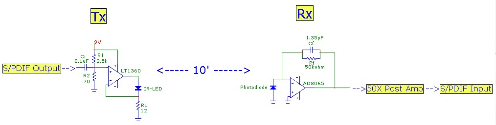
This article aims to illustrate a basic optical LED wireless link for transmitting high-definition (HD) S/PDIF digital audio streams. Circuit designs for both the transmitter (optical modulator) and receiver are provided, utilizing cost-effective op-amp configurations. Specific components are listed,...
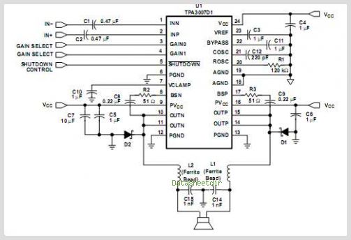
The TPA3112D1 is a 25-W efficient Class-D audio power amplifier designed for driving a bridge-tied speaker. It incorporates advanced EMI suppression technology, allowing the use of cost-effective ferrite bead filters at the outputs while complying with EMC requirements. The...