
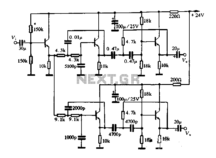
Single Transistor Audio Mixer Circuit

This audio mixer circuit employs a single transistor to facilitate the mixing of audio signals. The transistor operates in a common emitter configuration, where the input audio signals are fed to the base terminal. The base current controls the transistor's operation, allowing it to amplify the audio signals effectively.
The use of a base-driven transistor enables the circuit to achieve a high input impedance, making it suitable for interfacing with various audio sources without significantly loading them. The emitter current control mechanism allows for better stability and linearity in the amplification process, ensuring minimal distortion of the audio signals.
In this design, resistors are typically used to set the biasing conditions for the transistor, ensuring that it operates in the active region. Coupling capacitors may be included at the input and output stages to block any DC components, allowing only the AC audio signals to pass through. This is crucial for maintaining the integrity of the audio signals being mixed.
The output of the mixer can be connected to subsequent stages in an audio amplification system, such as additional amplifiers or equalizers. The simplicity of this single transistor audio mixer makes it an ideal choice for basic audio mixing applications, providing an efficient and effective solution for combining multiple audio sources into a single output signal.This single transistor audio mixer is used in an amplifier circuit design with base driven transistor and with its emitter being current controlled, most o.. 🔗 External reference
Related Circuits

The automatic alarm circuit comprises a DTMF automatic dialing system, a password control circuit, a voice detection and alarm circuit, a telephone interface circuit, a power supply circuit, and a keyboard display circuit. The automatic dial-up alarm utilizes the...
This article describes a band-pass filter circuit diagram utilizing transistors. A band-pass filter is an essential electronic circuit that allows signals within a certain frequency range to pass while attenuating frequencies outside that range. The circuit typically consists of a...
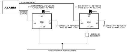
The following circuit illustrates the Ford Probe Single Wire Door Alarm System. This Single Door Locking Wire manages both LOCK and UNLOCK functions, indicating that the pulse wires must be connected to the same vehicle wire. The system primarily...
The circuit consists of inverter and charger sections. The inverter section utilizes the NE555 timer, while the charger section is based on the LM317 adjustable regulator. In the inverter section, the NE555 is configured as an astable multivibrator, generating...
The input impedance of AC-coupled operational amplifier (op-amp) circuits is primarily determined by the resistance that establishes the DC operating point. When using CMOS op-amps, the input impedance is high, reaching up to 10 MΩ in current op-amps. For...

The power is all in the timed switching process. There are two main principles I use of switching the radiant energy the John Bedini way. First, the SG/SSG, Icehouse unidirectional circuit or John Bedini Monopole with the School Girl...