
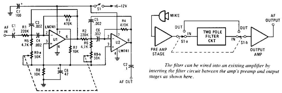
Variable Low-Pass Filter Circuit

The described circuit features a second-order low-pass filter configuration, which is designed to allow signals with a frequency lower than a specified cutoff frequency to pass through while attenuating frequencies higher than this threshold. The use of a 741 operational amplifier provides the necessary gain and buffering for the input signal, ensuring that the filter maintains signal integrity and performance.
The tuning capability of the filter, ranging from 2.5 kHz to 25 kHz, is achieved through the integration of ganged potentiometers, R1 and R2. These potentiometers allow simultaneous adjustment of resistance values, effectively altering the cutoff frequency of the filter. This tunability is particularly advantageous in audio applications where precise control over frequency response is required for tone shaping and signal processing.
In the schematic, the operational amplifier is configured in a feedback loop that includes capacitors and resistors arranged to define the filter characteristics. The capacitors determine the frequency response, while the resistors set the gain and the damping factor of the filter. The ganged potentiometers enable the user to modify both the resistance and the capacitance, allowing for fine-tuning of the filter's performance to suit specific audio needs.
Overall, this low-pass filter circuit is a versatile tool for audio engineers and hobbyists alike, providing a practical solution for managing audio frequencies in various applications, such as equalization, crossover networks, and other tone control systems. This second-order low-pass filter uses a 741 op amp and is tuneable from 2.5 kHz to 25 kHz. This circuit is useful in audio and tone control applications. R1 and 2 are ganged potentiometers.
Related Circuits
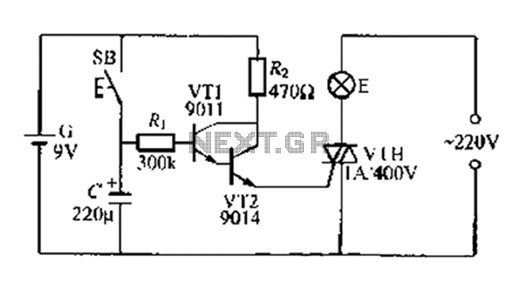
A delay circuit utilizing an electric lamp. Normally, the thyristor VTH remains off, and the lamp E does not illuminate. The lamp turns on when needed, controlled by the FSH, with the VT1 and VT2 components forming a composite...
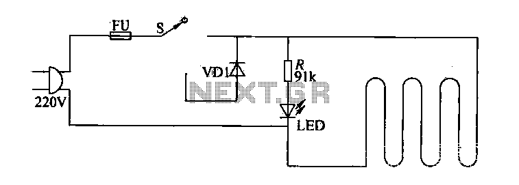
The circuit of electric blankets is controlled by switch S. When switch S is fully engaged, the entire supply voltage of 220V is applied to the heating wire, resulting in a high-temperature state. When a lower temperature is desired,...
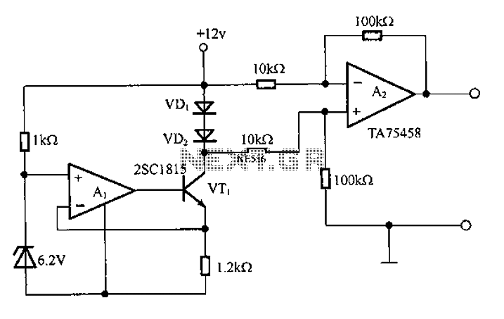
A diode is utilized in a temperature sensor application circuit. Silicon diodes VD1 and VD2 serve as the temperature sensors, exhibiting a temperature coefficient of silicon diodes. The circuit includes a constant current source, VT1, which provides a steady...
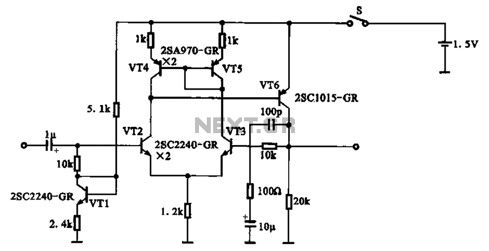
A 1.5V-powered microphone signal amplifying circuit is designed with a power supply for the microphone signal amplification. The circuit primarily consists of a differential amplifier formed by transistors VT2 and VT3. Additionally, VT6 functions as a common emitter voltage...
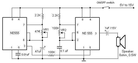
The primary components of this doorbell circuit include two NE555 timer integrated circuits (ICs). When the switch S1 is pressed momentarily, the loudspeaker emits a bell tone for the duration determined by the time period of the monostable multivibrator...
This variable-frequency audio bandpass filter is constructed using two 741 operational amplifiers connected in cascade. The two 741 op amps are configured as identical RC active filters and are cascaded to enhance selectivity. The filter's tuning range spans from...