
passive low pass filter remove RF

A low-pass filter is an essential component in radio frequency applications, particularly for crystal sets, where it is crucial to remove unwanted high-frequency signals that can interfere with the desired audio output. The design of a low-pass filter typically involves selecting resistor (R) and capacitor (C) values that determine the cutoff frequency (fc) of the filter.
The cutoff frequency is defined by the formula:
fc = 1 / (2πRC)
Where:
- fc is the cutoff frequency in Hertz (Hz),
- R is the resistance in ohms (Ω),
- C is the capacitance in farads (F).
To effectively remove RF interference, the cutoff frequency should be set below the frequency of the undesired RF signals while allowing the desired audio frequencies to pass through. For instance, if the target audio frequencies range from 300 Hz to 3 kHz, the cutoff frequency may be set around 3 kHz to ensure that the filter attenuates higher RF frequencies while preserving the audio signal.
To select appropriate resistor and capacitor values, one can rearrange the cutoff frequency formula. For example, if a capacitor value of 10 nF (10 x 10^-9 F) is chosen, the resistor value can be calculated as follows:
R = 1 / (2πfcC)
Assuming a cutoff frequency of 3 kHz:
R = 1 / (2π(3000)(10 x 10^-9)) ≈ 5.3 kΩ
Alternatively, if a standard resistor value of 4.7 kΩ is selected, the corresponding capacitor value can be calculated:
C = 1 / (2πRfc)
Using R = 4.7 kΩ and fc = 3 kHz:
C = 1 / (2π(4700)(3000)) ≈ 11.3 nF
The selection of resistor and capacitor values can thus be adjusted based on the specific requirements of the application, ensuring optimal performance of the low-pass filter in removing unwanted RF signals from the crystal set. It is also advisable to consider the tolerances and power ratings of the components to ensure reliability and efficiency in the circuit design.Looking for resistor value and capacitor value for low pass filter to remove RF. The application is removing undesired untuned RF from the crystal set .. 🔗 External reference
Related Circuits
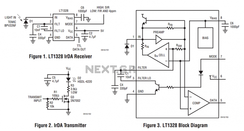
The LT1328, in the MS8 and SO-8 packages, contains all the necessary circuitry to convert current pulses from an external photodiode to a digital TTL output while rejecting unwanted lower frequency interference. The LT1328 plus five external components is...
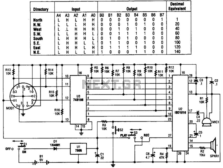
A talking compass consists of a Hall-effect direction sensor (MODI) and an ISD1016 analog audio storage device. It can store eight two-second announcements for each of the eight primary compass directions. The Talking Compass includes a digital compass (MODI),...
The circuit comprises four stages of active bandpass filtering, utilizing two A747 integrated-circuit dual operational amplifiers. It incorporates a simple threshold detector, consisting of diodes D1 and D2, positioned between stages 2 and 3 to minimize low-level background noise....
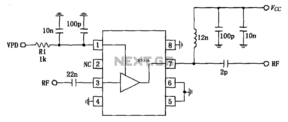
The circuit is based on an 880 MHz RF2347 low noise amplifier application. The radio frequency (RF) signal enters through input pin 3, and after amplification, the output is available at pin 7. The amplifier is directly coupled to...
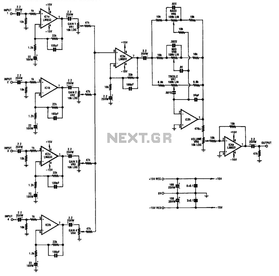
IC1-a, IC1-b, IC2-a, and IC2-b all operate with a gain of approximately 19. Their outputs are combined through level-control potentiometers, and the resulting signal is amplified by IC3-a before being sent to the tone-control stage IC3-b. Finally, the output...
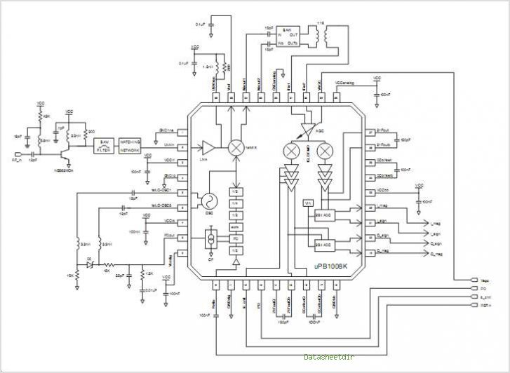
The PB1009K is a silicon monolithic integrated circuit (IC) designed for GPS receivers. This IC incorporates a complete voltage-controlled oscillator (VCO), a second intermediate frequency (IF) filter, a 4-bit analog-to-digital converter (ADC), and a digital control interface, all aimed...