
A Low Cost 4Mbps IrDA Receiver

The LT1328 is a highly integrated analog front-end device designed specifically for infrared data communication applications. It effectively converts photodiode current into a digital TTL signal while filtering out unwanted low-frequency noise, making it suitable for IrDA communication protocols. The device operates with minimal power consumption, requiring only a single 5V power supply and drawing a quiescent current of 2mA.
In operation, the photodiode (D1) generates a current in response to incoming infrared light, which is then converted to a voltage by the feedback resistor (RFB). The transconductance amplifier ensures that the DC level of the preamplifier is stabilized at VBIAS through a servo mechanism that dynamically adjusts the gain based on the incoming signal. This mechanism allows the LT1328 to effectively reject interference from ambient light sources, such as sunlight and artificial lighting, by implementing a high-pass filter.
The filter characteristics are adjustable via Pin 7, which allows for optimization of the circuit based on the desired data rate. For high data rates, Pin 7 should be set low, utilizing a 330pF capacitor (C4) to establish a corner frequency of 200kHz, suitable for data rates exceeding 115kbps. Conversely, for lower data rates, the capacitor (C1) can be switched in parallel with C4 when Pin 7 is brought high, lowering the corner frequency to 6.6kHz and accommodating data rates of 115kbps and below.
The LT1328 is capable of operating effectively within the full range of the IrDA standard, covering distances from 1cm to 1 meter and supporting light levels from 40mW/sr to 500mW/sr. The output of the device is inverted relative to the input signal, which is a critical consideration for the design of the overall transmitter circuit. The timing characteristics, such as the pulse width for data representation (1.6μs for a zero and no pulse for a one), are essential for maintaining compliance with IrDA specifications.
Overall, the LT1328 provides a robust solution for infrared communication systems, enabling the design of compact and efficient IrDA-compatible transmitters and receivers with minimal external component requirements.The LT1328, in the MS8 and SO-8 packages, contains all the necessary circuitry to convert current pulses from an external photodiode to a digital TTL output while rejecting unwanted lower frequency interference. The LT1328 plus fi ve external components is all that is required to make the IrDA-compatible receiver shown in Figure 1.
An IrDA-compatible transmitter can also be implemented with only six components, as shown in Figure 2. Power requirements for the LT1328 are minimal: a single 5V supply and 2mA of quiescent current.
LT1328 Functional Description Figure 3 is a block diagram of the LT1328. Photodiode current from D1 is transformed into a voltage by feedback resistor RFB. The DC level of the preamp is held at VBIAS by the servo action of the transconductance amplifier’s gm. The servo action only suppresses frequencies below the Rgm/CFILT pole. This highpass filtering attenuates interfering signals, such as sunlight or incandescent or fluorescent lamps, and is selectable at Pin 7 for low or high data rates.
For high data rates, Pin 7 should be held low. The highpass filter breakpoint is set by the capacitor C4 at f = 25/(2π • Rgm • C4), where Rgm = 60k. The 330pF capacitor (C4) sets a 200kHz corner frequency and is used for data rates above 115kbps. For low data rates (115kbps and below), the capacitance at Pin 2 is increased by taking Pin 7 to a TTL high.
This switches C1 in parallel with C4, lowering the highpass filter breakpoint. A 10nF capacitor (C1) produces a 6.6kHz corner. Signals processed by the preamp/gm amplifier combination cause the comparator output to swing low. IrDA SIR The LT1328 circuit in Figure 1 operates over the full 1cm to 1 meter range of the IrDA standard at the stipulated light levels. For IrDA data rates of 115kbps and below, a 1.6μs pulse width is used for a zero and no pulse for a one.
Light levels are 40mW/sr (Watts per steradian) to 500mW/sr. Figure 4 shows a scope photo for a transmitter input (bottom trace) and the LT1328 output (top trace). Note that the input to the transmitter is inverted; that is, transmitted light produces a high at the input, which results in a zero at the output of the transmitter.
The MODE pin (Pin 7) should be high for these data rates.
Related Circuits
The CD-ROM 48X RF AMP Chip serves as an RF pre-signal processor, handling signals from the optical pick-up. This chip processes the primary signal through a summing amplifier, an automatic gain control (AGC) block, and an equalization (EQ) block,...
This line-following robot sensor, also known as a surface scanner for robots, is a compact, stamp-sized infrared proximity detector designed for short-range detection (5-10 mm). It is built around a standard reflective opto-sensor, the CNY70 (IC1). In various applications,...
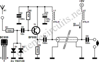
Function: step down the antenna impedance from high to 50 ohms and not, as would be expected, to effect a change from balanced to unbalanced. Component: .. In the context of antenna systems, impedance matching is crucial for maximizing power...
A very simple circuit for an FM receiver that does not require an integrated circuit (IC) and utilizes only a single transistor. The functionality of this transistor is uncertain. This design represents a regenerative or super-regenerative radio receiver. There...
There is a vast array of TX and RX modules available for microcontrollers. The least expensive option identified was priced at $9.99, which is reasonable, although there are memories of encountering FM receiver modules in the past. The TX (transmitter)...
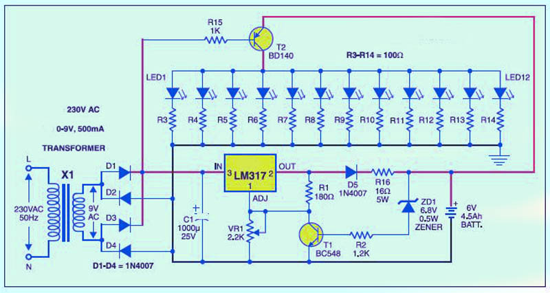
This is a low-cost circuit diagram for an emergency light utilizing a white LED. Components include an LM317 IC, a resistor, a transformer, an LED, and a variable resistor. The emergency light circuit using a white LED is designed for...