
PC 8Way Relay Board

Optional: 8 x 3way PCB mounted terminal mounts.
Kit Assembly:
Begin with the smaller items such as the 1N914 diodes and then the IC. You can then start on the 'taller' items like LEDs, resistors, regulator, bridge, green cap, etc. Once you have the basic components soldered in, carefully install the DB25 socket. Make sure that none of the pins get bent over as you're trying to wiggle everything into place. It's a nightmare to unsolder the socket if you make a mistake! Leave the relays until last.
Any 12 -15 volt 1 amp minimum AC or DC power supply can be used.
The control board is designed for a specific application, facilitating the operation of a 5-motor robot arm through the use of relays. The absence of input facilities indicates that this board is primarily focused on output control, making it a cost-effective solution for users requiring multiple relay outputs without the need for additional input functionalities.
The board features a printed circuit board (PCB) that houses various components. It includes eight single-pole double-throw (SPDT) relays, each rated for 12 volts, which are responsible for controlling the motors of the robot arm. The relays are activated by signals sent from the ULN2803 integrated circuit, which serves as a relay driver capable of controlling multiple outputs from a lower input voltage.
Power management is facilitated by the LM7812 voltage regulator, which ensures a stable output voltage of 12 volts from a higher input voltage, accommodating a range of 12 to 24 volts as specified. The bridge rectifier converts AC input power to DC, and the presence of diodes (1N4004 and 1N914) protects the circuit from back EMF generated by the relays and motors, ensuring reliability and longevity of the components.
LED indicators are included to provide visual feedback on the operational status of the relays, with current-limiting resistors ensuring proper operation without damaging the LEDs. The electrolytic capacitor (47uF) serves as a filter to smooth out voltage fluctuations, while the optional terminal mounts provide the flexibility for additional wiring configurations.
The assembly process is straightforward, starting with the smaller components to avoid complications when soldering larger components later. Special care should be taken during the installation of the DB25 socket to prevent pin damage, which can complicate repairs. The recommended power supply is crucial for ensuring the board operates efficiently, with a minimum of 1 amp current rating to support the relay activation and motor operation.
Overall, this control board represents a practical solution for users looking to manage multiple motors in a robotic application, emphasizing ease of assembly, cost-effectiveness, and robust performance.This board is designed specifically to control the 5-motor Robot Arm sold by Baycom Technologies. It has no input facilities, but it is less expensive than combining the I/O Board with the Relay sub-Board. If you need lots of relays and no input, this is the way to go. Parts List: 1 x PCB 8 x SPDT 12 volt Relays 1 x PCB mounted DB 25 Socket 1 x ULN2803 Integrated Circuit 1 x 1N4004 Diode 8 x 1N914 Diode 8 x 3mm Red LED 8 x 560 ohm 1/4 watt resistor 1 x 47uF Electrolytic Capacitor (up to 1000uF can be used depending on the power supply) 1 x 0.01uF (approx) Green Cap 1 x LM7812 Voltage regulator (T220 case) 1 x 1 amp Bridge Rectifier 1 x 2.1mm Power Socket 25 pin Serial Cable - Male to Male 12 - 24 volt power supply with 2.1mm Plug Optional: 8 x 3way PCB mounted terminal mounts. Kit Assembly: Begin with the smaller items such as the 1N914 doides and then the IC. You can then start on the 'taller' items like LEDs, resistors, regulator, bridge, green cap, etc. Once you have the basic components soldered in, carefully install the DB25 socket. Make sure that none of the pins get bent over as you're trying to wiggle everything into place. It's a nightmare to unsolder the socket if you make a mistake! Leave the relays until last. Any 12 -15 volt 1 amp minimum AC or DC power supply can be used. 🔗 External reference
Related Circuits
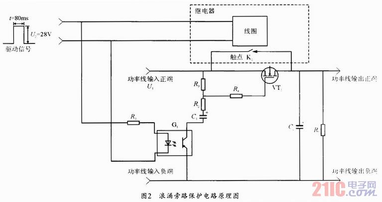
During the power-up of the apparatus, the capacitor is primarily responsible for the emergence of surge current. The schematic diagram of the principle is illustrated in Fig. 1. After K1 closes, the capacitor begins to charge, assuming that the...
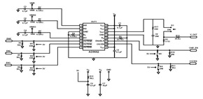
This schematic was created using a 2-layer evaluation board for the AD9662 3-Channel Laser Diode Driver. This device is primarily utilized in high-performance CD-DVD recordable drives and for laser diode current switching. The AD9662 is a specialized integrated circuit designed...
This single-sided prototyping board offers an economical solution for developing and testing projects utilizing Atmel's 20-pin series microcontrollers (89Cx051 & AVR). The circuit diagram of the prototyping board is illustrated in Figure 1. All port connections are accessible for...
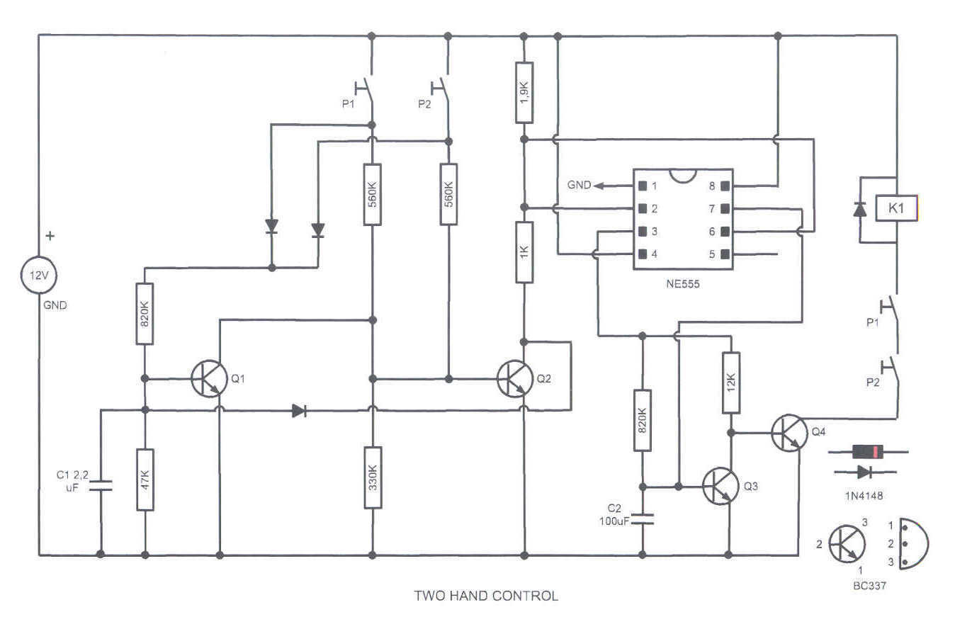
This circuit turns on a relay when two buttons are pressed at the same time. The relay backs off after a few seconds, then the buttons have to be released and pressed again. This feature is often required in...
Controlling a relay with an STM32 microcontroller involves using a 4N33 opto-isolator for electrical isolation. The relay coil requires approximately 250 mA, necessitating the use of an MPS222 transistor for switching. The GPIO configuration inverts the logic when used...
The circuit requires a double pole, double throw relay in conjunction with a single transistor to allow toggling the relay with a momentary push button. One set of relay contacts is used to control the load, while the other...