
Single Transistor Relay Toggle Circuit

The described circuit utilizes a double pole, double throw (DPDT) relay in combination with a single transistor to facilitate the toggling of the relay through a momentary push button. The design incorporates two sets of contacts within the relay: one set is dedicated to controlling the load, while the second set provides feedback to maintain the relay's state, either activated or deactivated.
When the momentary push button is pressed, a small current flows through the transistor, which in turn energizes the relay coil. This action switches the relay contacts, allowing the load to be powered. The feedback mechanism is achieved through the second set of contacts, which can be used to create a self-latching circuit. This means that once the relay is activated, it will remain in that state even after the push button is released, until it is toggled again by pressing the button.
The circuit design also allows for multiple push buttons to be connected in parallel. This feature enables control of the relay from various locations, providing flexibility in operation. Each push button, when pressed, will send a signal to the transistor to toggle the relay, ensuring that the load can be controlled conveniently from different points.
In terms of component selection, the relay should be rated appropriately for the load it will control, and the transistor must be capable of handling the current required to energize the relay coil. Additionally, resistors may be needed to limit the current to the transistor and protect the circuit from potential damage. Proper circuit layout and grounding practices should be followed to ensure reliable operation and minimize interference.The circuit requires a double pole, double throw relay in conjunction with a single transistor to allow toggling the relay with a momentary push button. One set of relay contacts is used to control the load, while the other is used to provide feedback to keep the relay activated or deactivated.
Several push buttons can be wired in parallel to allow toggling the relay from different locations.. 🔗 External reference
Related Circuits
This is a Mini MW (Medium Wave) Transmitter circuit. This circuit consists of a combination of transistors SA103 and SA101. These transistors are used as oscillators. The Mini MW Transmitter circuit is designed to operate in the medium wave band,...
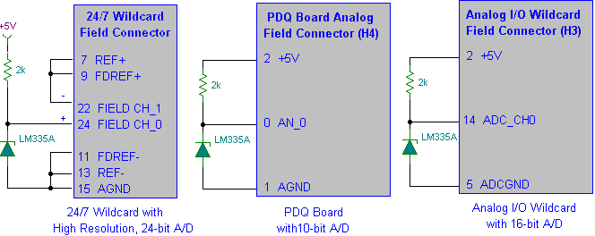
Interfacing the LM335A temperature sensor with A/D converters involves measuring temperature using the LM35 and LM335A sensors alongside the 9S12 HCS12 microcontroller. This process includes analyzing both calibrated and uncalibrated temperature errors of integrated circuit temperature sensors. The LM335A is...
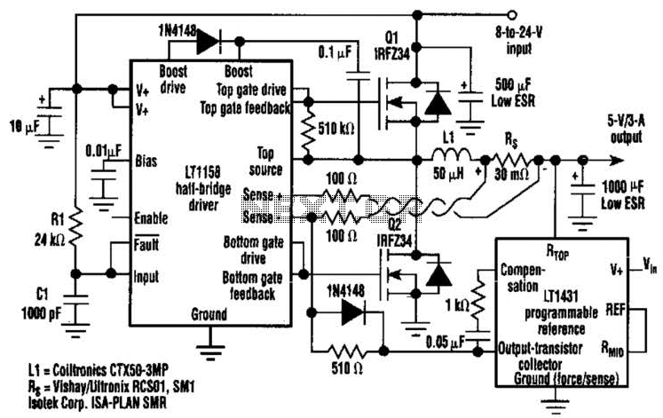
This regulator achieves 90% efficiency with a 12-V input and a 5-V output. It utilizes the LT1158 and LT1431 components from Linear Technology, Inc. High efficiency is accomplished by synchronously switching two power MOSFETs in a step-down switching regulator....
An aerial voltage power supply with a continuously adjustable stabilized output ranging from 0 to 30 VDC. The circuit also incorporates an electronic current limiter that effectively controls the output current from a few milliamperes (2 mA) to a...
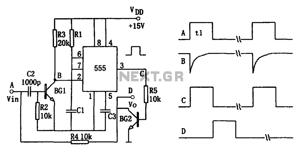
The pulse-width detection circuit is illustrated in the figure and consists of a differential circuit (R2, C2), an amplifier (BG1), a single stabilizing circuit (555, R1, C1), and various other components. The pulse signal Vin (depicted as waveform A)...
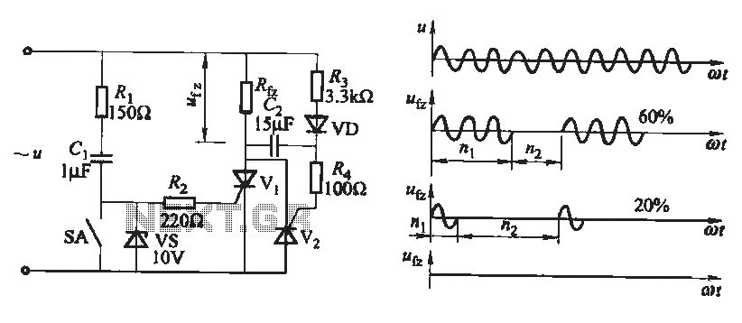
The output waveform of the thyristor zero trigger circuit is a sine wave, which does not generate electromagnetic interference like a phase-shift trigger circuit. This circuit serves as a basic thyristor power adjustment mechanism. In the circuit diagram, the...