
PC-BASED CANDLE IGNITOR lighting candle using computer

The PC-based candle ignitor project integrates hardware and software components to allow a computer to control the ignition of a candle using a 555 timer integrated circuit (IC). The 555 timer is configured in a monostable or astable mode, depending on the desired functionality, to generate a pulse that can trigger a relay or a transistor. This relay or transistor acts as a switch to control a heating element or ignitor that ignites the candle.
The circuit diagram typically includes the 555 timer connected to various components such as resistors, capacitors, and a control mechanism that interfaces with the computer. The computer communicates with the circuit through a serial or parallel interface, sending commands to activate the 555 timer. The software code written in C is responsible for user input, processing, and sending signals to the hardware.
In a practical application, the user can initiate the ignition process through a graphical user interface (GUI) on the computer. The software may include safety features such as timers or confirmation prompts to ensure safe operation. The overall design emphasizes reliability and safety, making it suitable for educational purposes and demonstrations of electronic control systems.
This project serves as an excellent learning tool for computer students, providing hands-on experience with both hardware circuitry and software programming, reinforcing concepts in electronics and embedded systems.PC based candle ignitor is a pc based verified project for computer student using 555 lighting candle using computer circuit diagram with software code in C . 🔗 External reference
Related Circuits
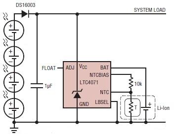
A simple solar-powered battery charger circuit can be designed using the LTC4071 Li-Ion/Polymer Shunt Battery Charger System with Low Battery Disconnect. When VCC reaches the programmed float voltage (4.1V with ADJ floating), the LTC4071 shunts excess current not used...
Additional examples for connecting transceivers to a computer for SIMPLEX software operations are detailed in the pc_tx.bmp file included in the simplex.zip file. The provided information indicates that the pc_tx.bmp file contains visual representations or diagrams that illustrate various methods...
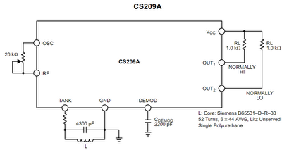
The operation principle of the proposed metal detector circuit is straightforward yet intriguing. The detection function is activated by sensing a decrease in the quality factor (Q) of the LC network associated with the circuit when a metal object...

The circuit operates using binary signal statuses of "1" and "0". It also incorporates a frequency generator. The circuit described utilizes a binary signaling system, which is fundamental in digital electronics. The binary states "1" and "0" represent the two...
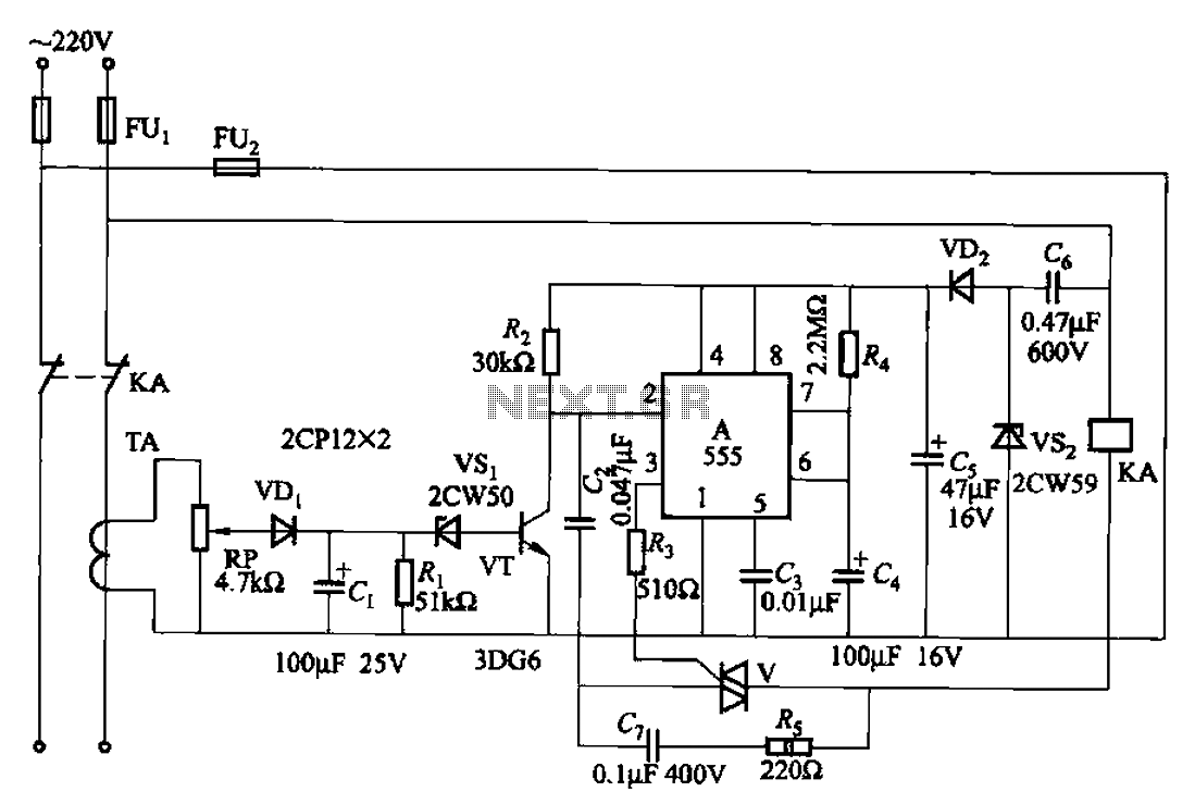
The 555 limit circuit, which is an integrated electrical circuit, is designed to manage large electrical loads. It automatically disconnects power when the load exceeds a predetermined threshold. Once the load is reduced below this threshold, power is restored...
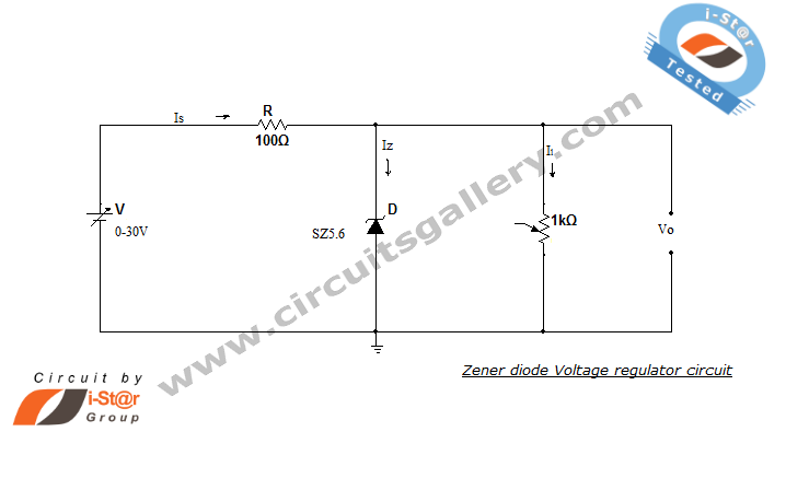
A Zener diode regulator is a fundamental electronic circuit valuable for hobbyists. This circuit provides a regulated output voltage, suitable for biasing other circuit components. The Zener diode operates in the reverse breakdown region, maintaining a nearly constant voltage...