
PC Based Frequency Meter

This frequency measurement technique is particularly advantageous for applications requiring precise frequency analysis over a broad range. The use of a PC's parallel port for data acquisition simplifies the interfacing process, allowing for straightforward implementation without the need for complex hardware setups. The cascaded binary counters effectively reduce high-frequency signals to a manageable level, enabling accurate time period measurements. The software's role in data processing is critical, as it not only facilitates the measurement process but also ensures that errors are promptly identified and reported.
In practical applications, the system can be integrated into various electronic projects where frequency measurement is essential, such as signal processing, telecommunications, and audio analysis. The choice of MOD counter directly influences both the measurement range and precision, making it imperative to select the appropriate counter based on the specific requirements of the application. Additionally, the software's capability to analyze the data bit-wise enhances its robustness, allowing for better detection of square waveforms and improving overall measurement reliability.
In summary, this technique provides a reliable and efficient method for frequency measurement, leveraging both hardware and software components to achieve accurate results across a wide frequency spectrum. The careful selection of components and parameters is crucial for optimizing performance and ensuring that the system meets the desired specifications.A simple technique for measuring frequencies over quite a wide frequency range and with acceptable accuracy limits using a PC. It follows the basic technique of measuring low frequencies, i. e. at low frequency, period is measured for a complete wave and frequency is calculated from the measured time-period.
Cascaded binary counters are use d for converting the high-frequency signals into low-frequency signals. The parallel port of a computer is used for data input from binary counters. This data is used for measuring time and calculating the frequency of the signal. The block diagram shows the basic connections of the counters and parallel port pin numbers on 25-pin D` connector of a PC (control register 379 Hex is used for input). External hardware is used only for converting the higher frequency signals into low frequency signals.
Thus, the major role in frequency-measurement is played by the software. The PC generates a time-interrupt at a frequency of 18. 21 Hz, i. e. after every 54. 92 millisecond. Software uses this time-interrupt as a time-reference. The control register of the PC`s parallel port is read and the data is stored continuously in an array for approximately 54. 9 ms using a loop. This stored data is then analysed bit-wise. Initially, the higher-order bit (MSB or the seventh-bit) of every array element is scanned for the presence of a complete square wave.
If it is found, its time period is measured and if not then the second-highest order bit (sixth bit) is scanned. This operation is performed till the third bit and if no full square wave is still found, an error message is generated which indicates that either there is an error in reading or the frequency signal is lower than 19 Hz.
Lower three bits of the control register are not used. When a wave is found, along with its time-period and frequency components, its measurement precision in percentage is also calculated and displayed. Number of data taken in 54. 9 ms is also displayed. As stated above, the lower starting range is about 19 Hz. Data is read for approximately 54. 9 ms. Thus, the lowest possible frequency that can be measured is 1/. 0549 Hz. Lower range depends only on the sampling time and is practically fixed at 19 Hz (18. 2 Hz, to be precise). Upper range depends on factors such as value of the MOD counter used and the operating frequency range of the counter IC.
If MOD-N counter is used (where N is an integer), upper limit (UL) of frequency is given by UL=19xN5 Hz. Thus for MOD 16 counters UL@20 MHz, and for MOD 10 counters UL@1. 9 MHz. Care should be taken to ensure that this upper limit is within the operating frequency range of counter IC used.
Precision of measurement is a machine-dependent parameter. High-speed machines will have better precision compared to others. Basically, precision depends directly upon the number of data read in a standard time. Precision of measurement varies inversely as the value of MOD counter used. Precision is high when MOD 10 counters are used in place of MOD 16 counters, but this will restrict the upper limit of frequency measurement and vice-versa. Be the first of your friends to get free diy electronics projects, circuits diagrams, hacks, mods, gadgets & gizmo automatically each time we publish.
Your email address & privacy are safe with us ! 🔗 External reference
Related Circuits
The LM3915 is a monolithic integrated circuit that senses analog voltage levels and drives ten LEDs providing a logarithmic 3 dB/step analog display. LED current drive is regulated and programmable, eliminating the need for current limiting resistors. The IC...
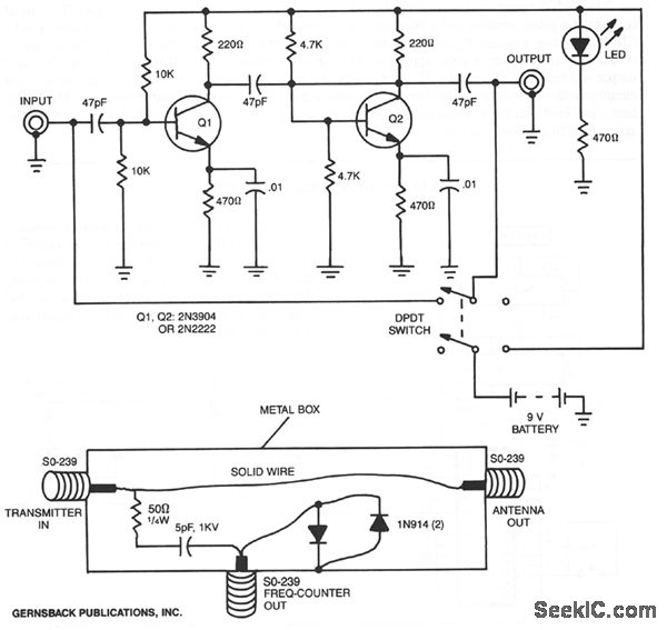
By utilizing a preamplifier with a short length of shielded cable and clip leads, signals that typically do not produce a readout can generate precise and stable readouts on the counter. A DPDT switch is incorporated to bypass the...
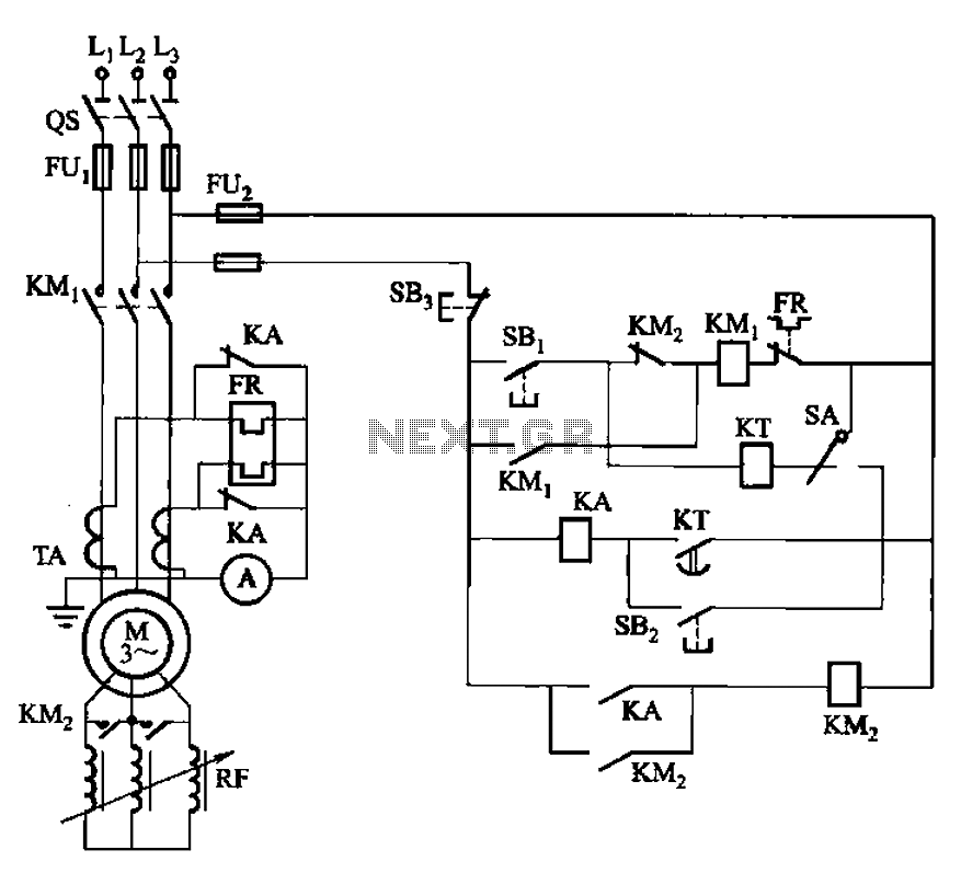
The circuit shown in Figure 3-164 can operate in both manual and automatic modes. During startup, the normally closed contact of relay KA is shorted, which affects the heating element to avoid prolonged startup times that could lead to...
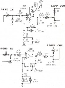
Preamplifiers are utilized to amplify low-level signals, such as those from microphones and tape heads, before they are sent to power amplifiers. Power amplifiers typically exhibit lower sensitivity. The frequency response can also be adjusted and optimized at the...
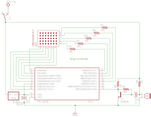
Tengu derives its name from a mythical Japanese creature known for getting into mischief. However, this Tengu is more earthly in nature. It responds to voice and sounds, changing its facial features depending on the intensity of the sound....
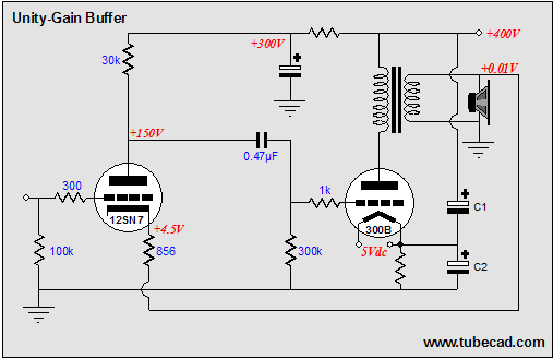
The solid-state, unity-gain power buffer is a well-known concept, but corresponding tube equivalents are less common. While super cathode followers, which are complex and augmented cathode followers with a gain of 0.99, have a long history with various designs...