
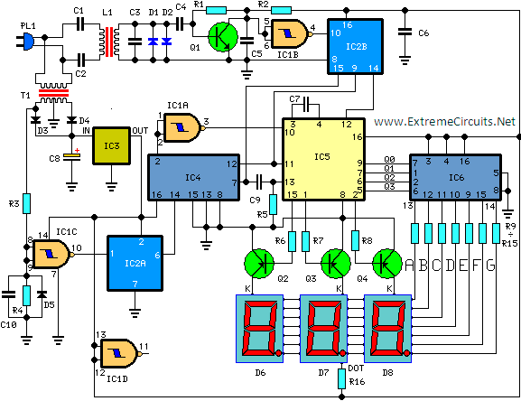
PC based frequency meter

The circuit described utilizes a straightforward design that prioritizes ease of use and cost-effectiveness, making it accessible for general users. The absence of isolation may be a concern in some applications, but the protective diodes (1 and 2) help mitigate risks associated with voltage spikes or reverse polarity, enhancing the circuit's reliability.
The inclusion of a 20MHz crystal oscillator module is beneficial for applications that require precise timing or frequency calibration. While this component is not necessary for basic functionality, it serves as an important tool for fine-tuning the circuit’s performance.
The prescaler, primarily functioning as a down counter, allows for the manipulation of frequency signals, which can be crucial in various electronic applications. AC coupling is integrated to block DC components from the input signal, ensuring that only the alternating current is processed. The DC trigger adjustment feature provides flexibility in tuning the circuit to respond appropriately to different signal levels.
The use of an optocoupler is a critical aspect of this circuit, as it provides electrical isolation between different sections, thereby protecting sensitive components from high voltages or noise that may be present in the signal path.
For power supply considerations, the choice between a hybrid isolation unit or a component-based design allows for customization based on the specific requirements of the application. The transformer salvaged from an energy-efficient lamp demonstrates a resourceful approach to component selection, promoting sustainability in circuit design.
Efficiency is noted as a limitation of this circuit, and the implementation of a shunt regulator on the output helps manage this by stabilizing the output voltage and current. Resistor R9 plays a vital role in monitoring the shunting current, ensuring that the circuit operates within safe parameters. The detection of a 12mA shunting current indicates that the circuit is functioning as intended, providing a reliable output while maintaining simplicity and cost-effectiveness.The simple circuit offers no isolation, but the simplicity of the circuit combined with cost of sound cards and the fact that diodes 1 and 2 add a good measure of protection makes this circuit ideal for the average user. Notice the physical hardware includes a 20MHz crystal oscillator module. This is not required to make the circuit work, but is i ncluded for calibration purposes. ( Stop the doubt before it makes you go batty ). The prescaler consists primarily of a down counter. AC coupling is provided together with a DC trigger adjustment. An opto coupler provides the signal isolation. The power supply could be a complete hybrid 5Volt to 5Volt isolation unit, or as in this case a component based design. The transformer used is a base drive transformer savaged from a 11W energy efficient lamp. If I remember correctly mine comes from a Phillips unit. The circuit is not particularly efficient, and as a result a simple shunt regulator can be used on the output.
I use R9 to detect the shunting current. In my case it sits at 12mA. 🔗 External reference
Related Circuits
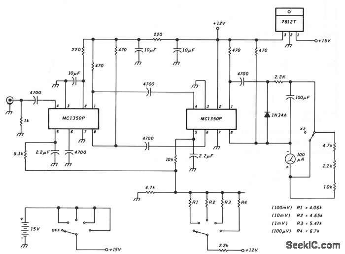
This schematic illustrates a peak-reading diode voltmeter that is powered by two amplification stages. A 100 µF capacitor is utilized to create a substantial time constant, which ensures effective damping of the meter. The restricted differential output voltage, combined...
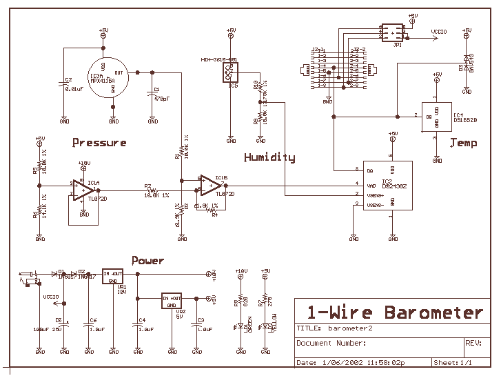
The Bray Barometer requires manual calibration for voltage offset and gain. Although practical on the workbench, these devices are most likely mounted in inconvenient locations making secondary adjustment difficult. The Bray Barometer uses potentiometers for offset and gain adjustments....
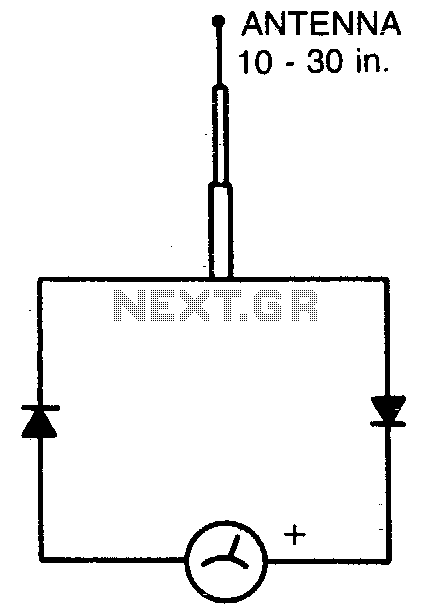
The circuit is frequency selective and has been utilized across frequency ranges from 2 meters to 160 meters. The telescoping antenna can be adjusted to its shortest length when operating at 2 meters to maintain the needle position on...
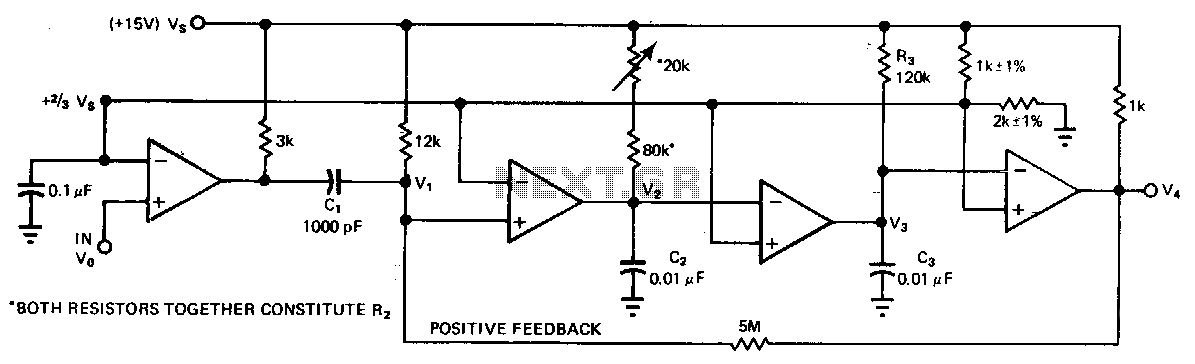
A quad comparator serves as the foundation for a frequency detector that is both faster and more cost-effective than more complex alternatives utilizing frequency-to-voltage converter chips. Positive feedback through a 5 MΩ resistor enables the circuit to detect changes...
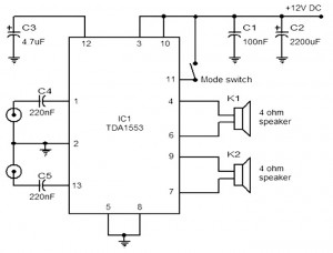
The provided schematic represents a car stereo amplifier circuit that can be utilized in cars or other vehicles. The circuit is based on the TDA1553, which is a Class-B audio amplifier. This circuit is straightforward, consisting solely of the...
This circuit is designed for precise measurement of temperature in degrees Celsius. It includes a transmitter section that converts the output voltage from the sensor, which is proportional to the temperature being measured, into a frequency signal. This frequency...