
SENSITIVE RF VOLTMETER

The described circuit comprises several critical components that work together to deliver accurate voltage readings while maintaining meter stability. The peak-reading diode voltmeter operates by first amplifying the input signal through two stages of amplification, which enhances the sensitivity of the measurement. The use of a 100 µF capacitor is crucial as it determines the time constant of the circuit, allowing for a smooth response to voltage changes while avoiding excessive oscillations or overshoot. This is particularly important in applications where transient voltages may be present.
The design incorporates an overdamped meter mechanism, which is essential for preventing the needle from sticking at maximum deflection when there is a sudden change in the input voltage or when the user mistakenly selects an inappropriate measurement range. This feature significantly improves the usability of the voltmeter, especially in field applications where quick adjustments may be necessary.
The inclusion of an SPST toggle switch for additional series resistance allows the user to extend the measurement range of the voltmeter. This X2 function effectively doubles the sensitivity range, providing more flexibility in measuring varying voltage levels without compromising accuracy. The resistance values indicated in the schematic are tailored for a specific configuration that utilizes a 100 µA meter with a 1500 Ω internal resistance, ensuring optimal performance and compatibility.
Overall, this peak-reading diode voltmeter schematic is designed to provide reliable and accurate voltage measurements across a range of conditions, making it a valuable tool in electronic testing and diagnostics.This schematic shows a peak-reading diode voltmeter driven by two stages of amplification. A 100- F capacitor provides a fairly large time constant, which results in satisfactory meter damping. The limited differential output voltage coupled with an overdamped meter prevents most needle pinning when you select an incorrect range position, or make
other errors. An SPST toggle switch selects additional series resistance. This X2 function gives some more overlap of the sensitivity ranges. The resistance values shown are correct for use with a 100- A meter with 1500- © internal resistance. 🔗 External reference
Related Circuits
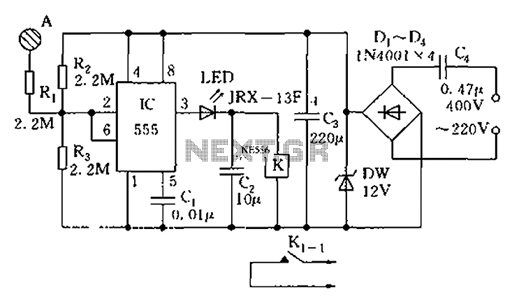
The touch sensor switch circuit diagram features a step-down rectifier circuit, a 555 timer, and flip-flops. When a hand touches the metal sheet A, the sensor signal activates the internal comparator of the 555 timer, setting the output to...

This design circuit is for converting voltage to frequency. Typically, frequency meters are used in speed sensors, tachometers, and for measuring recurring signals. The frequency to voltage converter (FVC) can transform voltage into either a digital or analog tachometer....
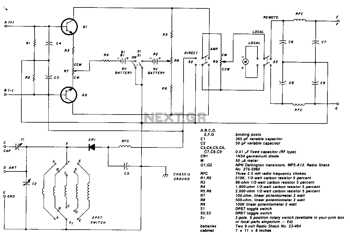
The two-pole, five-position switch, coils, and 365-pF variable capacitor cover a range from 1.5 to 30 MHz. The amplifier uses Darlington npn transistors whose high beta of 5000 provides high sensitivity, with SL used as the amplifier on/off switch....
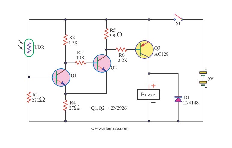
This circuit activates a warning when it becomes dark, functioning as a light-sensitive switch. The essential electronic components include the 2N2926 and AC128 transistors. The described light-sensitive switch circuit is designed to detect ambient light levels and activate an output...
The figure below illustrates a schematic of a highly sensitive microphone circuit designed to amplify faint sounds from a distance. The circuit exhibits significant sensitivity and offers substantial gain to weak audio signals. The microphone circuit typically consists of several...
The voltage that controls a V/F converter will be displayed when a frequency counter is used, which is directly proportional to the input voltage over a 1-second interval. A Voltage-to-Frequency (V/F) converter is a critical component in various electronic applications,...