
PC computer based frequency meter circuit diagram

The frequency measurement technique described employs a systematic approach to convert high-frequency signals into a format suitable for accurate measurement using standard PC hardware. The use of binary counters allows for effective scaling down of the frequency to a manageable level, facilitating the measurement process.
The implementation of the parallel port for data acquisition is a practical choice, given its availability in many PC architectures. The method leverages the time interrupt generated by the PC, which acts as a consistent time reference for the measurement process. This design ensures that the timing remains stable and reliable, which is crucial for accurate frequency calculations.
The analysis of the stored data bit-wise allows for a thorough examination of the signal waveform, ensuring that only complete square waves are considered for measurement. This step is critical to avoid inaccuracies that could arise from noise or incomplete signals. The error handling mechanism provides feedback to the user, indicating potential issues with the signal being measured, thus enhancing the robustness of the system.
The choice of MOD counters plays a significant role in determining both the upper and lower frequency limits of the measurement system. MOD 10 counters offer high precision at the cost of a lower upper frequency limit, while MOD 16 counters allow for higher frequency measurements but with reduced precision. This trade-off must be carefully considered based on the specific application requirements.
Overall, this frequency measurement technique utilizing a PC is an effective solution for a range of applications requiring frequency analysis, combining hardware and software elements to achieve reliable performance.Here is a simple technique for measuring frequencies over quite a wide frequency range and with acceptable accuracy limits using a PC. It follows the basic technique of measuring low frequencies, i. e. at low frequency, period is measured for a complete wave and frequency is calculated from the measured time-period.
Cascaded binary counters are use d for converting the high-frequency signals into low-frequency signals. The parallel port of a computer is used for data input from binary counters. This data is used for measuring time and calculating the frequency of the signal. The block diagram shows the basic connections of the counters and parallel port pin numbers on 25-pin D connector of a PC (control register 379 Hex is used for input). External hardware is used only for converting the higher frequency signals into low frequency signals.
Thus, the major role in frequency-measurement is played by the software. The PC generates a time-interrupt at a frequency of 18. 21 Hz, i. e. after every 54. 92 millisecond. Software uses this time-interrupt as a time-reference. The control register of the PC s parallel port is read and the data is stored continuously in an array for approximately 54. 9 ms using a loop. This stored data is then analysed bit-wise. Initially, the higher-order bit (MSB or the seventh-bit) of every array element is scanned for the presence of a complete square wave.
If it is found, its time period is measured and if not then the second-highest order bit (sixth bit) is scanned. This operation is performed till the third bit and if no full square wave is still found, an error message is generated which indicates that either there is an error in reading or the frequency signal is lower than 19 Hz.
Lower three bits of the control register are not used. When a wave is found, along with its time-period and frequency components, its measurement precision in percentage is also calculated and displayed. Number of data taken in 54. 9 ms is also displayed. As stated above, the lower starting range is about 19 Hz. Data is read for approximately 54. 9 ms. Thus, the lowest possible frequency that can be measured is 1/. 0549 Hz. Lower range depends only on the sampling time and is practically fixed at 19 Hz (18. 2 Hz, to be precise). Upper range depends on factors such as value of the MOD counter used and the operating frequency range of the counter IC.
If MOD-N counter is used (where N is an integer), upper limit (UL) of frequency is given by UL=19xN5 Hz. Thus for MOD 16 counters UL@20 MHz, and for MOD 10 counters UL@1. 9 MHz. Care should be taken to ensure that this upper limit is within the operating frequency range of counter IC used.
Precision of measurement is a machine-dependent parameter. High-speed machines will have better precision compared to others. Basically, precision depends directly upon the number of data read in a standard time. Precision of measurement varies inversely as the value of MOD counter used. Precision is high when MOD 10 counters are used in place of MOD 16 counters, but this will restrict the upper limit of frequency measurement and vice-versa. Disclaimer: All the information present on this site are for personal use only. No commercial use is permitted without the prior permission from authors of this website. All content on this site is provided as is and without any guarantee on any kind, implied or otherwise.
We cannot be held responsible for any errors, omissions, or damages arising out of use of information available on this web site. The content in this site may contain COPYRIGHTED information and should not be reproduced in any way without prior permission from the authors.
🔗 External reference
Related Circuits
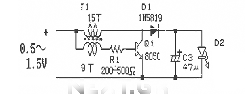
This is a simple and easy-to-build DC-DC driver circuit designed for a single flashlight battery, operating at a parametric voltage of 1.5V. The input current is 90mA, while the light-emitting diode (LED) current is 26mA or higher. The circuit...
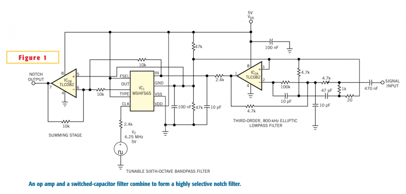
Although you can obtain universal, resistor-programmable switched-capacitor filters that are configurable as notch filters, most cannot operate at bandwidths higher than 100 kHz. Further, the typically 16- to 20-pin packages do not include a continuous-time, antialiasing filter to prevent...
This straightforward high-level design illustrates the structure of the product. The integrated circuit reacts to button presses and detects temperature through a probe, displaying the temperature on an LCD and activating a buzzer upon completion. A more detailed diagram...
This circuit utilizes a relay to control a water pump, enabling automatic level management of a water reservoir or well. The shorter steel rod functions as the "water high" sensor, while the longer rod serves as the "water low"...
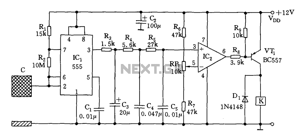
The switch circuit consists of a capacitive oscillator, an integration network, and a comparator circuit that controls a relay. When a body comes close to the induction plate, the inductive capacitance to ground increases, causing the 555 astable multivibrator...
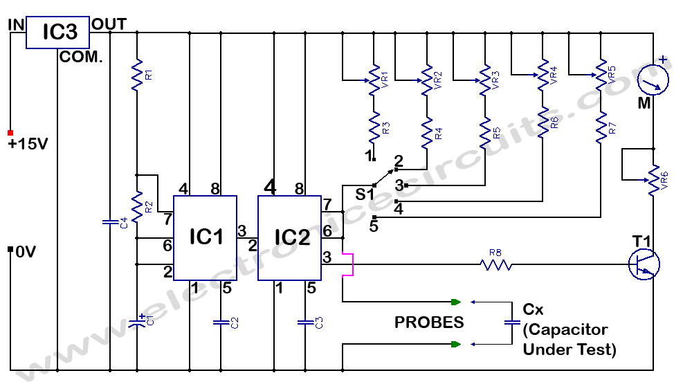
Capacitance Meter Circuit Using 555. It directly reads capacitance in the range of 100 pF to 10 µF. IC1 and IC2 operate as an astable multivibrator, generating a frequency that is dependent on the capacitance being measured. The capacitance meter...