
PC Fan Speed Controller - For a Low-Noise PC

A fan speed controller circuit can significantly enhance the efficiency of cooling systems in personal computers by adjusting the fan's operation according to thermal requirements. The design typically incorporates a temperature sensor, such as a thermistor or a digital temperature sensor, which monitors the internal temperature of the PC.
The output from the temperature sensor is fed into a microcontroller or a comparator circuit that processes the temperature data. Depending on the temperature readings, the controller adjusts the voltage supplied to the fan using a pulse-width modulation (PWM) technique. This method allows for precise control of the fan speed, reducing unnecessary noise and power consumption when full cooling capacity is not required.
In a basic implementation, the circuit may consist of the following components:
1. **Temperature Sensor**: A thermistor or a digital sensor like the LM35, which provides an output voltage proportional to the temperature.
2. **Microcontroller or Comparator**: An IC, such as an Arduino or LM358, that interprets the temperature data and generates a PWM signal.
3. **PWM Driver Circuit**: A transistor or MOSFET that receives the PWM signal and controls the power delivered to the fan.
4. **Fan**: A DC fan that operates at varying speeds based on the PWM signal.
The circuit can be designed with adjustable thresholds, allowing users to set the desired temperature ranges for fan activation. Additionally, implementing a feedback loop can further refine performance, ensuring that the fan speed dynamically adjusts to rapid changes in temperature, thus optimizing cooling efficiency and prolonging the lifespan of PC components.
This fan speed controller circuit not only improves thermal management but also contributes to quieter operation and energy savings, making it a valuable addition to any PC system.The fan runs constantly in many PCs, which may not even be necessary. A simple controller circuit can regulate the fan speed according to demand. This not.. 🔗 External reference
Related Circuits
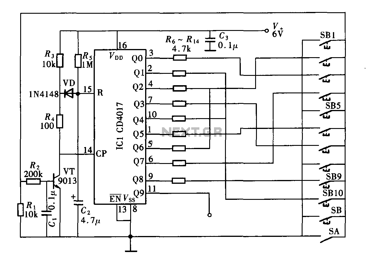
The digital controller features a nine-digit password system and includes a total of 11 keys. This comprises four pseudo-code keys and seven overlay keys, each of which has two valid key options. The total number of possible passwords is...
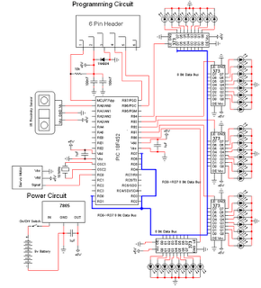
The personal radar system utilizes the PIC microcontroller PIC18F452 as a hobby project. The attached circuit diagram of the radar may appear simple; however, careful analysis of the PIC18F452 radar circuit is necessary to prevent damage. This personal radar...
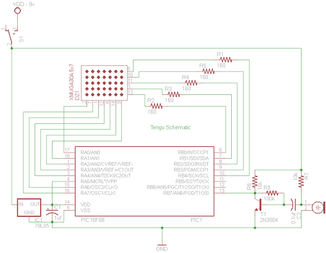
Tengu derives its name from a mythical Japanese creature known for getting into mischief. However, this Tengu is more earthly in nature. It responds to voice and sounds, changing its facial features depending on the intensity of the sound....
The automatic sprinkler controller circuit consists of a power supply circuit and a humidity measurement and control circuit, as illustrated in the accompanying figure. The power supply circuit includes a power transformer (T), rectifier diodes (VD1 to VD4), filter...
The HC-06 module is a slave mode serial Bluetooth data link manufactured by CSR. In this project, a mobile phone communicates with the AT89C2051 microcontroller via the HC-06 module. The complexity of the communication has been encapsulated within a...
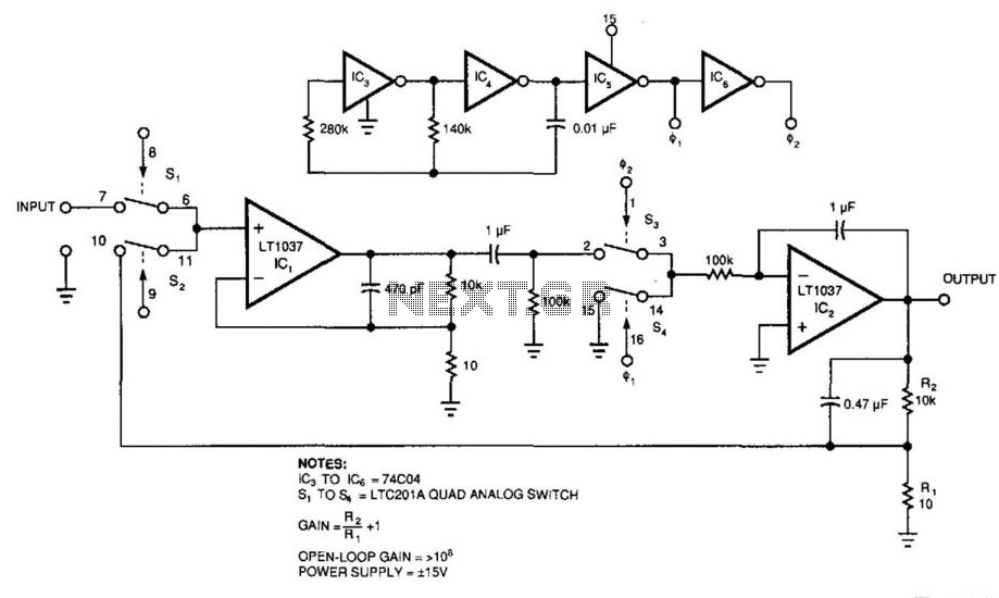
Figure 39-2's circuit combines a low-noise operational amplifier, IC1, with a chopper-based carrier-modulation scheme to achieve a low-noise, low-drift DC amplifier whose performance exceeds any currently available monolithic amplifier. The amplifier's offset is less than 1 mV, and its...