
PC interfaced Security System

The HUB provides 4 network feeds. One feed can be used for monitoring the network traffic or manually accessing the modules using the PC interface (below). In an expanded system, those 2, 3 or 5 way phone splitters (check your local Dollar Store) can be used as necessary to get the phone cable to any number of modules.
The Hub also provides 2 power inputs (diode isolated) for possible battery backup, the master pull-up resistor for the network data line, and fuse protection.
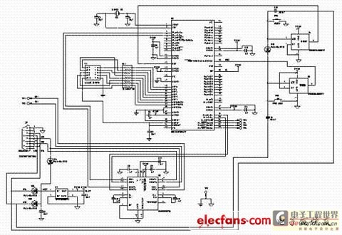
Here are the schematic and layout.
The PC INTERFACE translates 19.2 K Baud serial signals to and from all of the modules. This is a great tool for debugging the system. The network traffic is all in ASCII and can be viewed with any terminal program. Also, commands can be entered directly into the system to individually check the operation of each module.
Here are the schematic, layout, source file and object file.
The 4 wires in the phone cable are designated as follows:
BLACK power ground
RED 12-16 volt unregulated power feed
GREEN network ground
YELLOW network signal
Standard phone cable, connectors, and junction boxes are used where needed. All cable must be 'straight through' with each connector having the colors in the same positions (black, red, green, yellow). Buying the cable in bulk and using a stake-on hand tool is handy for making all cables just the right length and ensuring the wire order is always correct.
Each module within the system is designed to operate independently while still being part of a larger network. The use of RJ-11 connectors facilitates easy connection and disconnection of modules, allowing for flexibility in system design and deployment. The unregulated 12-16 volt power feed is suitable for long-distance transmission without significant voltage drop, as the individual modules incorporate a 5-volt regulator to ensure proper operation of their components.
The HUB serves as the central point for communication and power distribution. It can manage multiple modules simultaneously, providing a robust framework for home automation. The inclusion of diode isolation for power inputs ensures that the system can seamlessly switch to battery backup when necessary, enhancing reliability during power outages.
The PC INTERFACE acts as a bridge between the user and the networked modules, enabling real-time monitoring and control of the system. The use of 19.2 K Baud serial communication ensures that data transmission is efficient and allows for easy debugging through ASCII commands. This interface is essential for developers and users who need to diagnose issues or configure settings for individual modules.
Overall, this modular home control system exemplifies an efficient design approach, leveraging standard components for ease of installation and maintenance while providing a flexible and scalable solution for home automation needs.Creating a modular, networked, home control system was greatly simplified by using common 4-wire phone cable with stake-on connectors. The cable feeds both power and network signals to the various modules. Each module is made on a single sided circuit board with RJ-11 connectors (for the network / power) along with other connectors as needed.
This eliminates the need for placing power feeds (wall worts) for each of the modules. The entire system runs on one power feed. Since the power feed is at least 12 volts (unregulated), very long cable runs can be used to connect to various modules. Each module has its own 5 volt regulator to run the circuit. It also means that the entire system can be run from a single 12 volt battery if the power is out. To use any of the modules in this system, you need to provide these two modules that support the operation of all of the others The HUB provides 4 network feeds. One feed can be used for monitoring the network traffic or manually accessing the modules using the PC interface (below).
In an expanded system, those 2,3 or 5 way phone splitters (check your local Dollar Store) can be used as necessary to get the phone cable to any number of modules. The Hub also provides 2 power inputs (diode isolated) for possible battery backup, the master pull-up resistor for the network data line, and fuse protection.
Here are the schematic and layout. The PC INTERFACE translates 19.2 K Baud serial signals to and from all of the modules. This is a great tool for debugging the system. The network traffic is all in ASCII and can be viewed with any terminal program. Also, commands can be entered directly into the system to individually check the operation or each module. Here are the schematic, layout, source file and object file. The 4 wires in the phone cable are designated as follows: BLACK power ground RED 12-16 volt unregulated power feed GREEN network ground YELLOW network signal Standard phone cable, connectors, and junction boxes are used where needed.
All cable must be 'strait through' with each connector having the colors in the same positions (black,red,green,yellow). Buying the cable in bulk and using a stake-on hand tool is handy for making all cables just the right length and ensuring the the wire order is always correct.
🔗 External reference
Related Circuits
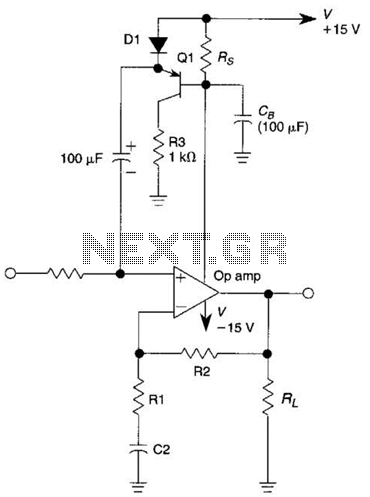
This circuit was requested by several correspondents. Its purpose was to obtain more power than the siren circuit already available on this website (One-IC two-tones Siren) and to avoid the use of ICs. A complementary transistor pair (Q2 &...
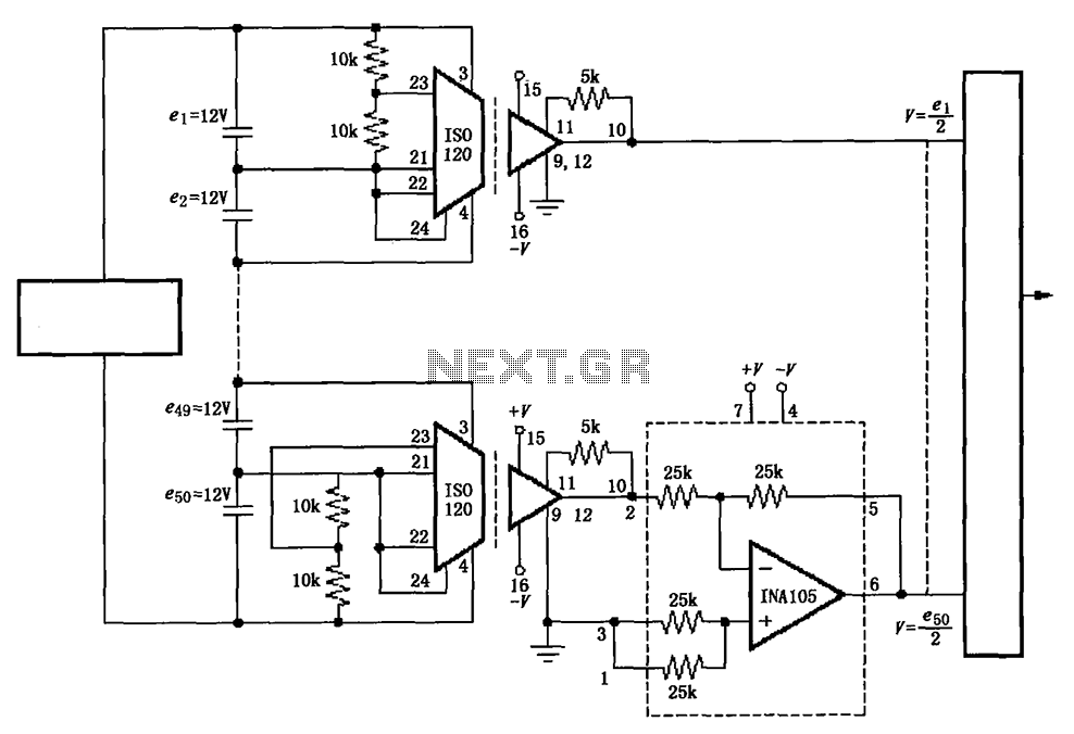
The circuit utilizes the ISO120 and INA105 instrumentation amplifiers to create a battery monitoring system for a 600V battery setup composed of 50 series-connected 12V batteries. This circuit is designed to detect charging and discharging conditions to prevent overcharging...
This circuit is an Automatic Gain Control (AGC) system designed for audio-frequency signals. AGC systems typically consist of three main components: an amplifier, a rectifier, and a controlled impedance. In this particular circuit, the functions of both the amplifier...
The component is deformed due to various thermal influences during processing, which compromises the original machining accuracy and introduces errors. In precision finishing, the effect of thermal deformation is particularly significant, leading to processing errors that can exceed 40%....
SigmaTel's STAC9721 and STAC9723 are general-purpose 18-bit stereo, full-duplex audio CODECs that adhere to the AC'97 (Audio Codec 97 Component Specification Rev. 2.1) specifications. These devices utilize SigmaTel's proprietary Sigma-Delta technology to achieve a DAC signal-to-noise ratio (SNR) exceeding...
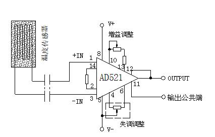
This text discusses the MSC1210 microcontroller as the core of a high-accuracy temperature measurement system, which includes signal processing and communication capabilities. The system is designed for easy expansion, allowing for accurate measurements and fast data acquisition. The hardware...