
PC mains switch

Please Note Although not shown in the PC wiring loom above, it is essential that you use a 1A in-line fuse in the +12V supply lead. I have been advised by a reader that many PC power supplies have no current limiting for the 12V supplies, and an accidental short-circuit can cause extremely high current to flow. This will cheerfully burn the insulation off the wiring, and may also damage the power supply.
As an alternative to a fuse, a fusible resistor may be used. A 10 ohm fusible resistor will limit the maximum current to 1.2A (at almost 15W) which will protect wiring and the power supply. You could also use a 10 ohm 10W resistor. Normally, it will remain completely cold, but will provide protection in case of a fault. Unlike a fuse or fusible resistor, the 10W resistor will not fail but it will get very, very hot if the fault is maintained. I'll leave it to the individual to decide which method to use, but one of the methods described must be used. As you can see, I used masking tape as an insulator. After drilling and de-burring, I wrapped the bracket with 4 turns of ordinary masking tape. You can use anything you like here, but be sure to check that the insulation is intact before connecting the unit to the PC. From the socket, run a couple of wires for +12 and earth (ground) to a male line connector to match a spare disk connector, and that's it for the PC side of the project. The mains switching uses a relay. The relay must have a 12V coil, and contacts rated for at least your mains supply voltage, with a current rating that will accommodate the maximum expected current. The relay can be incorporated into a standard multi-way power distribution board, but you will probably need to remove the wiring to the last outlet to provide room for the relay and input socket. Note that the wiring shown in the grey shaded section must be totally separated from the mains wiring as shown above. This is the safety barrier, and it is imperative for your safety (and that of others) that no part of this wiring should be anywhere near the mains distribution. I suggest that a minimum clearance of 10mm be used between the mains and control wiring.
This project utilizes the internal 12V supply of a personal computer (PC) to control peripheral devices through a relay mechanism. The relay serves as a switch that allows for the connection or disconnection of power to various devices based on the operational state of the PC. When the PC is powered on, the relay activates, allowing power to flow to connected peripherals such as monitors, sound systems, modems, and printers. Conversely, when the PC is turned off, the relay disengages, cutting power to these devices.
The design requires careful attention to safety, particularly in the separation of low-voltage control circuits from high-voltage mains wiring. A relay with a 12V coil and appropriately rated contacts for the mains voltage is essential. The relay's contacts must also be capable of handling the maximum current expected from the connected devices.
To ensure reliable operation and prevent damage from potential short circuits, an in-line fuse rated at 1A is recommended in the 12V supply line. Alternatively, a 10-ohm fusible resistor can be employed to limit current, providing an additional layer of protection. It is important that the insulation of the wiring is verified to prevent accidental shorts, particularly at the connection points of the 3.5mm socket.
For installation, the wiring leading from the socket to the power distribution board must be adequately insulated and separated from mains wiring to maintain safety standards. A minimum clearance of 10mm is advised to prevent any electrical hazards. The entire assembly should be tested for functionality and safety before connecting to the mains supply.This project couldn't be any simpler if it tried. Using the PC's internal 12V supply to operate a relay, it is 100% reliable. If the PC is on, the peripherals are on and vice versa - it can't be otherwise (unless the relay fails). Other solutions have been suggested in magazines and the like, often using a USB port. The problem is that some PCs don't switch off the 5V supply to USB devices even when the PC is off. The auxiliary supply within the ATX power supply unit maintains a low power 5V supply all the time, and this is sometimes used for the USB ports to charge cordless mouses (meece?) or other devices.
I use my unit to switch off the power to my monitor and PC sound system, and the one I built for SWMBO (she who must be obeyed) shuts down her modem and printer. Any peripheral device can be controlled provided the total current rating for the power board is not exceeded.
Naturally enough, additional units can be used if you need to switch off a lot of equipment - the relay loading on the 12V supply is minimal, so several relays can be used if needed. There is nothing special about the PC wiring, but it is a very good idea to make sure that the 3.5mm socket is insulated from the panel.
Although the polarity is not important, it is strongly recommended that the black lead (earth / ground) connects to the jack sleeve (the threaded section that goes through the panel). The +12V supply connects to the tip. If you happen to get it wrong somehow, the insulation will prevent a short circuit of the 12V supply.
If the supply is shorted, it will probably cause an instant supply shut-down and possible data loss. Please Note Although not shown in the PC wiring loom above, it is essential that you use a 1A in-line fuse in the +12V supply lead. I have been advised by a reader that many PC power supplies have no current limiting for the 12V supplies, and an accidental short-circuit can cause extremely high current to flow.
This will cheerfully burn the insulation off the wiring, and may also damage the power supply. As an alternative to a fuse, a fusible resistor may be used. A 10 ohm fusible resistor will limit the maximum current to 1.2A (at almost 15W) which will protect wiring and the power supply. You could also use a 10 ohm 10W resistor. Normally, it will remain completely cold, but will provide protection in case of a fault. Unlike a fuse or fusible resistor, the 10W resistor will not fail but it will get very, very hot if the fault is maintained.
I'll leave it to the individual to decide which method to use, but one of the methods described must be used. As you can see, I used masking tape as an insulator. After drilling and de-burring, I wrapped the bracket with 4 turns of ordinary masking tape. You can use anything you like here, but be sure to check that the insulation is intact before connecting the unit to the PC.
From the socket, run a couple of wires for +12 and earth (ground) to a male line connector to match a spare disk connector, and that's it for the PC side of the project. The mains switching uses a relay. The relay must have a 12V coil, and contacts rated for at least your mains supply voltage, with a current rating that will accommodate the maximum expected current.
The relay can be incorporated into a standard multi-way power distribution board, but you will probably need to remove the wiring to the last outlet to provide room for the relay and input socket. Note that the wiring shown in the grey shaded section must be totally separated from the mains wiring as shown above.
This is the safety barrier, and it is imperative for your safety (and that of others) that no part of this wiring should be anywhere near the mains distribution. I suggest that a minimum clearance of 10mm be used between the mains and control wiring. 🔗 External reference
Related Circuits
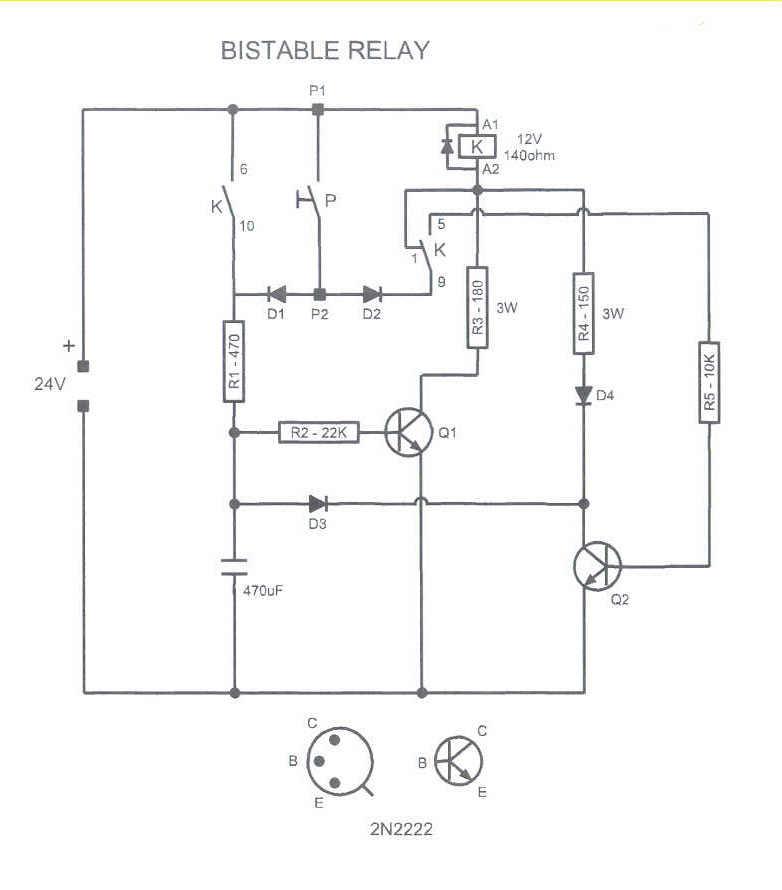
This circuit could be used to drive a monostable relay by a single momentary switch. Powered by 24 Volts, it works for a 12 Volts relay. When the button is pressed, Q1 is energized and the capacitor charges, while...
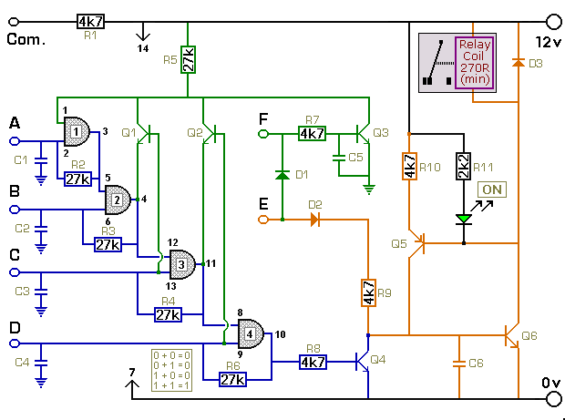
The key connected to "E" is used to energize the relay, while the four keys connected to A, B, C, and D are used to de-energize it. All other keys on the keypad are connected to "F". When "E"...
70 W switching power supply utilizing the KA2S0880 integrated circuit. Refer to the specified page for an explanation of the associated circuit diagram. The 70 W switching power supply designed with the KA2S0880 integrated circuit (IC) is a versatile solution...
This simple circuit, as shown in the schematic diagram, activates a switch using sound. It can be utilized for various applications, such as automatic sound-controlled disco lights or a car's LED light show. The transistor Q1 amplifies the audio...
Each audio/video output can be switched to any of the eight inputs separately. One module drives one audio/video output and has a 34-pin connector to plug into the system interface. Video operational amplifiers (OPAs) can be used on the...
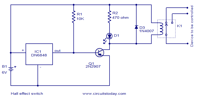
The circuit diagram presented is for a Hall Effect switch. The core component of this circuit is the Hall Effect sensor IC DN6848 from Panasonic. This integrated circuit features a Hall Effect sensor, a Schmitt trigger circuit, a power...