
Pc Password Protection Circuit

The described circuit functions as a security mechanism for personal computers, ensuring that unauthorized access is prevented during the boot process. The core of the circuit is a microcontroller or a dedicated security IC that monitors the input from a keypad or other input device where the password is entered.
Upon powering up, the circuit initializes and prompts the user for a password. The microcontroller compares the entered password against a pre-stored value in its non-volatile memory. If the correct password is entered, the circuit allows the PC to boot normally. In contrast, if the incorrect password is entered, the circuit increments a counter that tracks the number of failed attempts.
After three failed attempts, the circuit triggers a cold reboot of the PC, which can be achieved by controlling the power supply to the computer or by using a reset line. This mechanism ensures that the system is locked out temporarily, requiring the user to start the password entry process anew after the reboot.
The software component mentioned in the description is crucial for the configuration and management of the password system. It may provide functionalities such as setting the password, changing it, or even logging attempts for security auditing purposes. The software should be designed to interface seamlessly with the hardware, ensuring robust communication and minimal latency during the password verification process.
Overall, this circuit is an effective solution for enhancing the security of personal computers, particularly in environments where sensitive data is stored or accessed. With this circuit, a PC will be protected, requiring a password to boot. After three times, the computer will have to have a cold reboot and the password tried again. Software for this system is availableconsult the reference for further details.
Related Circuits
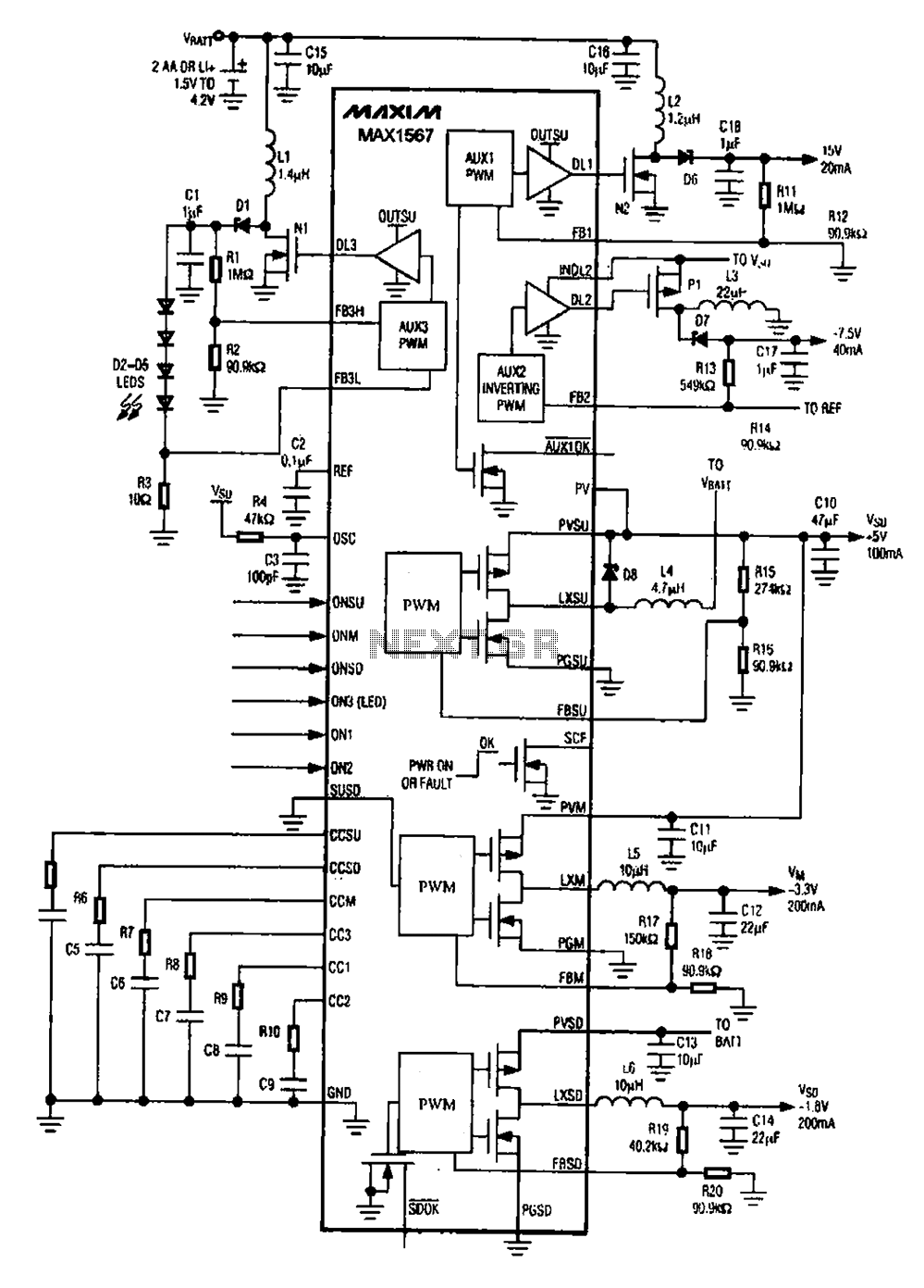
A brush 6-channel camera power supply circuit utilizing the MAX1566/1567. This circuit features a PWM generation system that is divided into six groups, with each group managing a separate channel. The circuit converts the DC voltage from the battery...

A flat mobile active car antenna is being tested with a Terratec Cinergy DT USB XS Diversity digital tuner. The antenna is designed to enhance signal reception for mobile digital television. The flat mobile active car antenna is engineered to...
For several years, a rear fog lamp has been mandatory for trailers and caravans to enhance visibility in foggy conditions. When this fog lamp is activated, the fog lamp of the towing vehicle must be turned off to prevent...

This simple wind charger circuit project is designed using the LTC1042 monolithic CMOS window comparator, manufactured by Linear Technology. The wind charger circuit utilizes wind power to generate the energy necessary for charging Ni-Cd or lead-acid batteries. When the...
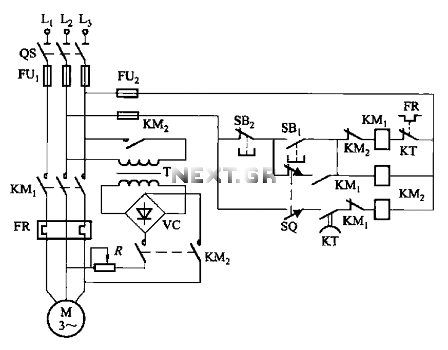
The circuit illustrated in Figure 3-136 incorporates a limit switch (SQ) that, when the motor operates a mechanical device to reach a predetermined position, cuts off the power and initiates dynamic braking for fast and accurate positioning. This configuration...

The infrared alarm system utilizes an infrared LED that emits invisible light. When this light is obstructed by an object, it triggers an alarm. The system comprises an infrared light-emitting circuit and a receiving circuit. The light-emitting diode (LED)...